 Honda Accord: Brake Pedal Position Switch Signal
Circuit Troubleshooting
1. Turn the ignition switch to ON (II).
2. Check the BRAKE SWITCH in the DATA LIST with the HDS.
Does it indicate OFF? YES
-Go to step 3.
NO
-lnspect the brake pedal position switch (see page 19-6).
3. Press the brake pedal, and check the BRAKE SWITCH in the DATA LIST with the HDS.
Does it change to ON? YES
-The brake pedal position switch signal circuit (BKSW line) is OK.
NO
-Go to step 1.
4. Turn the ignition switch to LOCK (0).
5. Jump the SCS line with the HDS.
6. Disconnect the brake pedal position switch 4P connector.
7. Disconnect ECM/PCM connector A (49P).
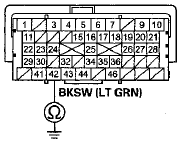
8. Check for continuity between ECM/PCM connector terminal A42 and body ground.
ECM/PCM CONNECTOR A (49P)

Terminal side of female terminals
Is there continuity? YES
-Repair short in the wire between the ECM/PCM (A42) and the brake pedal position switch. Replace the No. 10 HORN/STOP (20 A) fuse.B NO
-Go to step 9.
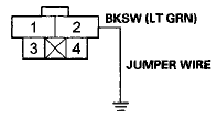
9. Connect brake pedal position switch 4P connector terminal No. 2 to body ground with a jumper wire.
BRAKE PEDAL POSITION SWITCH 4P CONNECTOR

Wire side of female terminals
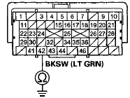
10. Check for continuity between ECM/PCM connector terminal A42 and body ground.
ECM/PCM CONNECTOR A (49P)

Terminal side of female terminals
Is there continuity? YES
-Repair open in the wire between the brake pedal position switch and the No. 10 HORN/STOP (20 A) fuse. Inspect the brake pedal position switch (see page19-6).
NO
-Repair open in the wire between the ECM/PCM (A42) and the brake pedal position switch.
 PSP Switch Signal Circuit
Troubleshooting
1. Start the engine, and let it idle.
2. Align the steering wheel straight ahead.
3. Check the PSP SWITCH in the DATA LIST with the
HDS.
Does it indicate ON?
YES-Go to step 4.
NO-Go to s ...
 Idle Speed Inspection
NOTE:
- Before checking the idle speed, check these items:
- The malfunction indicator lamp (MIL) has not been
reported on, and there are no DTCs.
- Ignition timing
- Spark plug ...
See also:
A/C Line Replacement
1.Discharge hose to the A /C compressor (6 x 1.0 mm): S.8 N-m (1.0 kgf-m, 7.2
Ibf-ft)
2.Discharge hose to the A /C condenser (6x1.Р’В© mm): 9.8 N-m f 1.0 kgf-m, 7.2
Ibf-ft)
3.Receiver lin ...
Rear Air Outlet Replacement
NOTE: Take care not to scratch the body.
1_ Remove the rear bumper (see page 20-260).
2. Release the hooks (A), then remove the rear air outlet
(B).
3. Install the air outlet by pushing on t ...
Ignition Switch Test
NOTE: SRS components are located in the area. Review
the SRS component locations 4-door (see page 24-21),
2-door (see page 24-23), and precautions and
procedures (see page 24-25) before doing repai ...
