 Honda Accord: Alternator and Regulator
Circuit Troubleshooting
Honda Accord: Alternator and Regulator
Circuit Troubleshooting
Special Tools Required
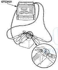
Alternator, Regulator, Battery, and Starter Tester OTC3131* ^Available through the Honda Tool and Equipment Program 888-424-6857
1. Make sure the battery connections are good and the battery is sufficiently charged.
2. Connect the alternator, regulator, battery & starter tester (OTC3131) to the battery as shown.
NOTE: The probe is used for alternator testing.
3. Start the engine. Hold the engine speed at 3,000 rpm with no load (in N or P (A/T model) or neutral (M/T model)) until the radiator fan comes on, then let it idle.
4. Do the CHARGING SYSTEM TEST.
Does the display indicate voltage within 13.5-”15.1 V and amperage of 87.5 A or more? YES-Go to step 5.
NO-lf the voltage is less than 13.5 V, go to alternator control circuit troubleshooting (see page 4-28). If the voltage is over 15.1 V and amperage is less than 87.5 A, replace the alternator (see page 4-32) or repair the alternator (see page 4-34).
5. Check the diode condition on the display.
Does the display indicate GOOD? YES-The diode is OK. Troubleshooting is complete.ll NO-lf the display indicates BAD, replace the alternator (see page 4-32) or repair the alternator (see page 4-34), then retest.B NOTE If the display indicates N/A, the diode pattern could not be diagnosed. Repeat the test. If N/A appears repeatedly, replace the alternator.
 Charging System Indicator
Circuit Troubleshooting
Charging System Indicator
Circuit Troubleshooting
troubleshooting the charging system indicator.
1. Turn the ignition switch to ON (II).
Does the charging system indicator come on?
YES-Go to step 2.
NO-Go to step 14.
2. Start the engine. ...
 Alternator Control Circuit
Troubleshooting
Alternator Control Circuit
Troubleshooting
NOTE: Do this troubleshooting if, in step 5 of the
alternator and regulator circuit troubleshooting (see
page 4-27), the battery voltage is less than 13.5 V.
* 1. Connect the Honda Diagnostic Sys ...
See also:
Connecting Rod Bolt Inspection
1. Measure the diameter of each connecting rod bolt at
point A and point B.
2. Calculate the difference in diameter between point A
and point B.
Point A-”Point B = Difference in Diameter
D ...
Clutch Pedal Position Switch
Replacement
M/T model
1 Disconnect the clutch pedal position switch connector
(A).
2. Loosen the locknut (B), then remove the clutch pedal
position switch (C).
3. Install the clutch pedal position switch ...
Reverse Lockout
6-speed manual transmission only
The manual transmission has a
lockout so you cannot accidentally
shift from any forward gear to
reverse while the vehicle is moving
at a certain speed. If you ...