 Honda Accord: Steering Gearbox Removal
Special Tools Required
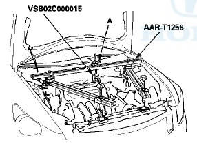
-Engine Hanger Adapter VSB02C000015*
•Engine Support Hanger, A and Reds AAR-T1256*
-Ball Joint Remover, 28 mm 07MAC-SL0A202
-Ball Joint Thread Protector, 12 mm 07AAF-SDAA100
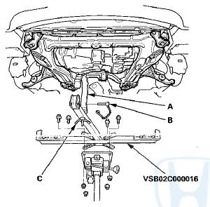
•Subframe Adapter VSB02C000016*
*: Available through the Honda Tool and Equipment Program, 888-424-6857.
SRS components are located in this area. Review the SRS component locations: 4-door (see page 24-21), 2-door (see page 24-23) and the precautions (see page 24-25) and procedures before doing repairs or service.
Note these items during removal: -Using clean solvent and a brush, wash any oil and dirt off the valve body unit, it's lines, and the end of the steering gearbox. Blow dry with compressed air.
-Be sure to remove the steering wheel before disconnecting the steering joint, or damage to the cable reel can occur.
-Lower the front subframe from the body, and remove the steering gearbox through the gap produced by lowering the front subframe.
1. Drain the power steering fluid (see page 17-28).
2. Do the battery terminal disconnection procedure (see page 22-91).
3. Raise and support the vehicle (see page 1-13).
4. Remove the front wheels.
5. Remove the driver's airbag (see page 24-211), and the steering wheel (see page 17-6).
6. Remove steering joint cover (A).
7. Loosen the upper steering joint bolt (A), and remove the lower steering joint bolt (B). Disconnect the steering joint (C) by sliding the steering joint into the column shaft (D). Tighten the upper steering joint bolt to hold the steering joint in place.
NOTE: Do not disconnect the steering joint from the column shaft.
8. Remove the center guide (A) (if equipped) from the top of the pinion shaft (B), and discard it.
10. Remove the hood support rod, then use it as shown to prop the hood in the wide-open position.
11. Remove the front grille cover:
-4-door (see page 20-274)
-2-door (see page 20-274)
12. Remove the strut brace (if equipped) (see page 20-306).
13. Remove the P/S heat shield (A).
14. Attach the engine hanger adapter (VSB02C000015) to the threaded hole in the cylinder head.
15. Install the engine support hanger (AAR-T1256), then attach the hook to the slotted hole in the hanger t adapter. Tighten the wing nut (A) by hand to lift and support the engine/transmission.
NOTE: Be careful when working around the windshield.
16. Remove the rear engine mount (A).
M/T
A/T
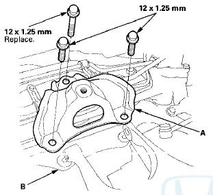
17. A/T: Remove the rear engine mount upper bracket (A) from the base bracket (B).
18. Remove the inlet line clamp bolt (A) and the return line clamp bolt (B).
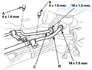
19. Loosen the flare nuts, and disconnect the inlet line (C) and the return line (D).
20. Remove the inlet line clamp bolt (A) and the return hose clamp bolt (B).
21. Release the return hose clamp (C)f and remove the return hose (D).
22. Remove the return line clamp bolt (A).
23. Release the return line clamp (B), and remove the return line (C).
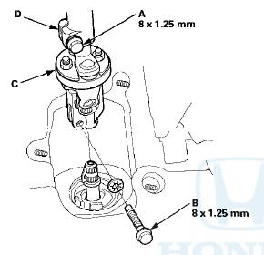
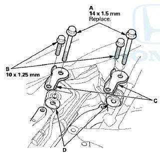
24. Remove the flange bolts from the passenger's side of the steering gearbox, then remove the gearbox mounting bracket (A) and mounting cushion (B).
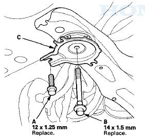
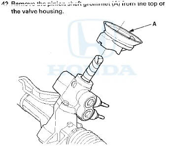
25. Remove the mounting bolts (A) and the flange bolts (B) from the driver's side of the steering gearbox, and remove the stiffener plates (C) and the washers (D).
26. Remove cotter pin (A) from the tie-rod end ball joint, then remove the nut (B) on both sides.
27. Disconnect the tie-rod end ball joint from the knuckle using the ball joint thread protector and the ball joint remover on both side (see page 18-10).
NOTE: Be careful not to damage the ball joint boot when installing the remover.
28. Raise the vehicle.
29. Remove the front splash shield (see page 20-291).
30. Remove exhaust pipe A (see page 9-9).
31. Remove the damper fork mounting nut (A) and the mounting bolt (B).
32. Attach the front subframe adapter (VSB02C000016) to the subframe by looping the strap (A) over the front of the subframe, then secure the strap with the stop (B), then tighten the wing nut (C).
33. Remove the front subframe middle mounting bolts on the passenger's side.
34. Remove the front subframe middle mount (A) on the driver's side.
35. Remove the flange nuts (A) from the lower transmission mount.
36. Remove the flange bolts (A) from the front subframe front stiffeners (B).
37. Loosen the front subframe mounting bolts (C) so they are about 20 mm (0.79 in) from the mounting surface.
Do not loosen the front subframe mounting bolts more than necessary.
38. Remove the flange bolts (A) and front subframe mounting bolts (B) from the front subframe rear stiffeners (C).
39. Lower the jack slowly until the front subframe has dropped about 69 mm (2.71 in).
40. Carefully move the steering gearbox (A) toward the driver's side until the pinion shaft clears the fenderwell opening on the body.
41. Remove the steering gearbox (A) through the fenderwell opening on the driver's side.
43. After removing the steering gearbox, make sure that no power steering fluid gets on the gearbox mount cushions, the gearbox housing, the surface of the front subframe, and stiffener. Wipe off any spilled fluid at once.
 Pump Overhaul
Exploded View
Replace the pump as an assembly if any of the parts indicated with an
asterisk (*) are worn or damaged.
Special Tools Required
-Attachment, 32 x 35 mm 07746-0010100
-Driver Handl ...
 Steering Gearbox Overhaul
Exploded View
Special Tools Required
-Cylinder End Seal Remover Attachment
07TAF-SZ50100
-Valve Seal Ring Sizing Tool 07NAG-SR3090A
-Sleeve Seal Guide, 35.9 x 37
07YAG-S2X0100
-Sizing Tool, ...
See also:
A/T Gear Position Indicator Panel Light
Harness Replacement
Type A Shift Lever
NOTE: The A/T gear position indicator panel light
harness and the park pin switch are not available
separately. Replace the A/T gear position indicator panel
light harness and t ...
A/C Compressor Relief Valve
Replacement
1. Recover the refrigerant with a
recovery/recycling/charging station (see page 21-80).
2. Raise the vehicle on a lift.
3. Remove the relief valve (A) and the O-ring (B). Plug
the opening to k ...
Front Fender Trim Replacement
2-door
NOTE:
- Take care not to scratch the front grille cover or the
body.
- When prying with a flat-tip screwdriver, wrap it with
protective tape to prevent damage.
- The left side is show ...