 Honda Accord: Valve Clearance Adjustment
Special Tools Required
. Locknut Wrench 07MAA-PR70120
. Adjuster 07MAA-PR70110
NOTE: Connect the Honda Diagnostic System (HDS) to the data link connector (DLC) and monitor the engine coolant temperature (ECT) sensor 1 with the HDS. Adjust the valve clearance only when the ECT sensor 1 temperature is less than 100 Р’В°F (38 Р’В°C).
1. Remove the cylinder head cover (see page 6-73).
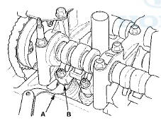
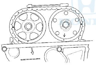
2. Set the No. 1 piston at top dead center (TDC). The punch mark (A) on the variable valve timing control (VTC) actuator and the punch mark (B) on the exhaust camshaft sprocket should be at the top. Align the TDC marks (C) on the VTC actuator and the exhaust camshaft sprocket.
3. Select the correct feeler gauge for the valve clearance you are going to check.
Valve Clearance
Intake: 0.21 - 0 . 2 5 mm (0.008-0.010 In)
Exhaust 0.25-0.29 mm (0.010-0.011 in)
4. Insert the feeler gauge (A) between the adjusting screw (B) and the end of the valve stem, and slide it back and forth; you should feel a slight amount of drag.
5. If you feel too much or too little drag, loosen the locknut with the locknut wrench and the adjuster, and turn the adjusting screw until the drag on the feeler gauge is correct.
6. Tighten the locknut to the specified torque, and recheck the clearance. Repeat the adjustment if necessary.
Specified Torque
Intake:
7 x 0.75 mm
14 N-m (1.4 kgf-m, 10 Ibfft) Apply new engine oil to the nut threads.
Exhaust:
7 x 0.75 mm
14 N-m (1.4 kgf-m, 10 Ibfft)
Apply new engine oil to the nut threads.
7. Rotate the crankshaft 180 Р’В° clockwise (camshaft pulley turns 90 Р’В°).
8. Check and, if necessary, adjust the valve clearance on the No. 3 cylinder.
9. Rotate the crankshaft 180 Р’В° clockwise (camshaft pulley turns 90 Р’В°).
10. Check and, if necessary, adjust the valve clearance on the No. 4 cylinder.
11. Rotate the crankshaft 180 Р’В° clockwise (camshaft pulley turns 90 Р’В°).
12. Check and, if necessary, adjust the valve clearance on the No. 2 cylinder.
13. Install the cylinder head cover (see page 6-74).
 VTC Actuator Inspection
1. Remove the cam chain (see page 6-62).
2. Loosen the rocker arm adjusting screws (see step 2 on
page 6-81).
3. Remove the camshaft holder (see step 3 on page
6-81).
4. Remove the intake c ...
 Crankshaft Pulley Removal and Installation
Special Tools Required
Handle, 6-25-660L 07JAB-001020B
Crankshaft Pulley Holder 07AAB-RJAA100
Socket, 19 mm 07JAA-001020A or equivalent
Removal
1 . Remove the front wheels.
2. Remove the splas ...
See also:
Steering
...
Electrical Compass Zone Selection
and Calibration
NOTE:
• You should do this procedure any time the electrical
compass unit is replaced.
• You should do this procedure in an open area away
from buildings, power lines, and other vehicl ...
Door Position Adjustment
NOTE: Check for a flush fit with the body, then check for
equal gaps between the front, rear, and bottom door
edges and the body. Check that the door and body edges
are parallel.
1. Place the ve ...