 Honda Accord: Steering Gearbox Overhaul
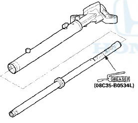
Exploded View
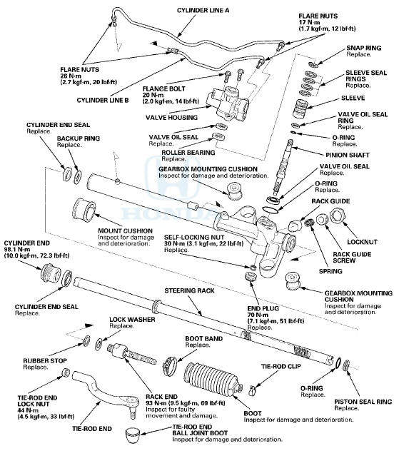
Special Tools Required
-Cylinder End Seal Remover Attachment 07TAF-SZ50100
-Valve Seal Ring Sizing Tool 07NAG-SR3090A
-Sleeve Seal Guide, 35.9 x 37 07YAG-S2X0100
-Sizing Tool, 36 07ZAG-S5A0100
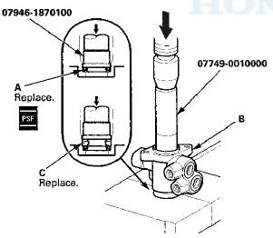
-Bearing Driver Attachment, 28 x 30 07946-1870100
-Driver Handle, 15x135L 07749-0010000
-Oil Seal Driver, 65 07JAD-PL9A100
-Bearing Driver Attachment, 30 mm 07746-0030300
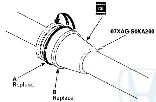
-Piston Seal Ring Guide 07XAG-S0KA200
-Sizing Tool, 42 07HAG-SF1020A or 07HAG-SF10200
-Pincers Oetiker 1098, commercially available
Disassembly
1. Remove the steering gearbox (see page 17-37).
2. Remove the tie-rod end from the rack end.
3. Drill a 4.0 mm (0.16 in) diameter hole about 2.5— 3.0 mm (0.10—0.12 in) in depth in the staked points (A) on the end plug (B) and the gearbox housing (C).
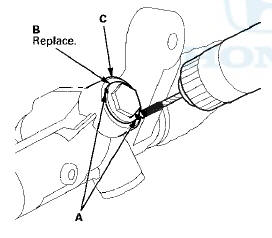
4. Remove the end plug (A) from the gearbox housing, then remove the self-locking nut (B) from the pinion shaft end.
5. Remove the boot bands (A) and tie-rod clips (B). Pull the boot away from the ends of the steering gearbox.

6. Hold the gearbox housing using a C-clamp (A) and wooden blocks (B) to a work bench as shown. Do not clamp the cylinder part of the gearbox housing in a vise.
7. Unbend the lock washers (A).
8. Hold the flat surface sections (A) of the steering rack (B) with one wrench, and unscrew both rack ends (C) with another wrench. Be careful not to damage the rack surface with the wrench.
9. Remove the lock washer (D) and rubber stop (E).
10. Loosen the locknut (A), then remove the rack guide screw (B).
11. Remove the spring (C), and the rack guide (D) from the gearbox housing.
12. Remove cylinder line A and B from the steering gearbox.
13. Drain the fluid from the cylinder fittings by slowly moving the steering rack back and forth.
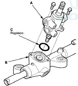
14. Remove the two flange bolts, then remove the valve body unit (A) from the gearbox housing (B). Remove the O-ring (C).
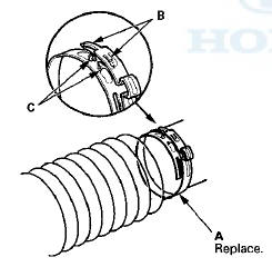
15. Apply vinyl tape (A) to the end of the steering rack and the gearbox housing. Drill a 3.0—4.0 mm
(0.12—0.16 in) diameter hole about 2.5—3.0 mm
(0.10—0.12 in) in depth in the staked point (B) on the
cylinder. Do not allow metal shavings to enter the
cylinder side on the gearbox housing. After removing the cylinder end (C), remove any burrs at the staked point.
NOTE: Apply vinyl tape (D) to the drill, and do not drill the depth more than necessary.
16. Hold the gearbox housing using a C-clamp (A) and wooden blocks (B) to a work bench as shown. Do not clamp the cylinder part of the gearbox housing in a vise. Remove the vinyl tape. Then remove the cylinder end (C).
17. Install a commercially available bearing separator (A) on the gearbox housing as shown
18. Place an appropriate size deep socket (B) on the steering rack (C).
19. Set the steering gearbox in a press so the gearbox housing side points upward, then press the cylinder end seal (D) and steering rack out of the steering gearbox. Hold the steering rack to keep it from falling when pressed clear. Be careful not to damage the inner surface of the cylinder side on the gearbox housing with the tool.
20. Carefully pry the piston seal ring (A) and O-ring (B) off the rack piston. Be careful not to damage the inside of the seal ring groove and piston edges when removing the seal ring.
21. Turn the cylinder end seal remover attachment so it fits through the rack guide hole of the gearbox housing, then position the seal remover on the backup ring (A). Make sure that the seal remover is securely positioned on the backup ring.
22 . Insert a 24" long 3/8" drive extension (A), on the cylinder end seal remover attachment. Place the gearbox housing in a press, then remove the backup ring (B) and cylinder end seal (C) from the gearbox housing by pressing on the 24" long 3/8" drive extension.
Note these items when pressing the backup ring and cylinder end seal: -Keep the tool straight to avoid damaging the cylinder wall. Check the tool angle, and correct it if necessary, when removing the backup ring and cylinder end seal.
-Use a press to remove the backup ring and cylinder end seal. Do not try to remove the backup ring and cylinder end seal by striking the tool; striking the tool would break the backup ring and cylinder end seal, and the backup ring and cylinder end seal would remain in the gearbox housing.
23. Apply vinyl tape (A) to the splines on the pinion shaft.
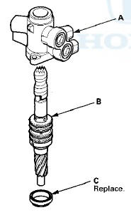
24. Separate the valve housing (A) from the pinion shaft/sleeve (B) and the valve oil seal (C).
25. With your finger, check the inner wall of the valve housing where the seal ring slides. If there is a step in the wall, the housing is worn, replace it.
26. Check for wear, burrs, and other damage to the edges of the grooves in the sleeve.
NOTE: The pinion shaft and sleeve are a precision matched set. If either the pinion shaft or sleeve must be replaced, replace both parts as a set.
27. Remove the snap ring (A) and the sleeve (B) from the pinion shaft (C).
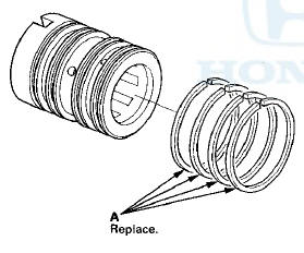
28. Using a cutter or an equivalent tool, cut and remove the four seal rings (A) from the sleeve. Be careful not to damage the edges of the sleeve grooves and outer surface when removing the seal rings.
29. Using a cutter or an equivalent tool, cut the valve seal ring (A) and O-ring (B) at the cutting groove position (C) in the pinion shaft. Remove the valve seal ring and O-ring. Be careful not to damage the edges of the pinion shaft groove and outer surface when removing the valve seal ring and O-ring.
30. Remove the valve oil sea! (A) and roller bearing (B) out of the valve housing using a hydraulic press and an appropriate size socket
31. Clean the disassembled parts with solvent, and dry them with compressed air. Do not dip rubber parts in the solvent.
Reassembly
32. Apply vinyl tape (A) to the splines and stepped portion of the shaft, and coat the surface of the vinyl tape with power steering fluid.
33. Fit the new O-ring (B) in the groove of the pinion shaft.
Then slide the new valve seal ring (C) over the shaft and in the groove on the pinion shaft.
34. Remove the vinyl tape, and apply power steering fluid to the surface of the valve seal ring (A).
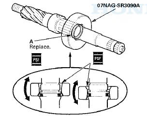
35. Apply power steering fluid to the inside of the valve seal ring sizing tool. Set the larger diameter end of the sizing tool over the valve seal ring, and move the sizing tool up and down several times to make the valve seal ring fit in the pinion shaft groove.
36. Remove the sizing tool, turn it over, slide the smaller diameter end over the valve seal ring. Move it up and down several times to make the valve seal ring fit snugly in the pinion shaft groove.
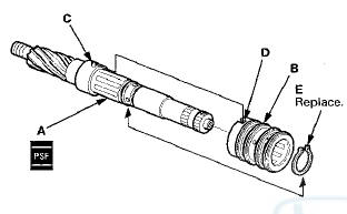
37. Apply power steering fluid to the surface of the sleeve seal ring guide. Slip two new seal rings (A) over the ring guide from the smaller diameter end, and expand them. Install only two rings at a time from each end of the pinion shaft sleeve (B).
Note these items when installing the seal ring: -Do not over-expand the seal ring. Install the resin seal rings with care so as not to damage them. After installation, make sure you contract the seal rings using the sizing tool.
-There are two types of sleeve seal rings; black and brown. Do not mix the different types of rings as they are not compatible.
38. Align the ring guide with each groove in the sleeve, and slide a sleeve seal ring into each groove. After installation, compress the seal rings with your fingers temporarily.
39. Apply power steering fluid to the seal rings on the sleeve, and to the entire inside surface of the sleeve seal ring sizing tool, then slowly insert the sleeve into the sizing tool.
40. Move the sleeve back and forth several times to make sure the seal rings fit snugly in the sleeve. Make sure the seal rings are not twisted.
41. Apply power steering fluid to the surface of the pinion shaft (A). Slide the sleeve (B) onto the pinion shaft by aligning the locating pin (C) on the pinion shaft with the cutout (D) in the sleeve. Then install the new snap ring (E) securely in the pinion shaft groove. Be careful not to damage the valve seal ring when installing the sleeve.
42. Apply power steering fluid to the seal ring lip of the new valve oil seal (A), then install the seal in the valve housing (B) using a hydraulic press and driver handle.
Install the seal with its grooved side facing the tool.
43. Press the new roller bearing (C) into the valve housing with a hydraulic press and attachment.
44. Apply vinyl tape (A) to the pinion shaft/sleeve (B), then coat the vinyl tape with power steering fluid.
45. Insert the pinion shaft/sleeve into the valve housing (C). Be careful not to damage the valve seal rings (D).
46. Remove the vinyl tape from the pinion shaft, then remove any residue from the tape adhesive.
47. Press the new valve oil seal (A) into the valve housing with a hydraulic press. Check that the pinion shaft/sleeve turns smoothly by hand after installing it.
48. Coat the piston seal ring guide with power steering fluid, then slide it onto the rack, big end first.
49. Position the new O-ring (A) and new piston seal ring (B) on the piston seal ring guide, then slide them down toward the big end of the tool.
Note these items during reassembly: -Do not over expand the resin seal rings. Install the resin seal rings with care so as not to damage them After installation, make sure you contract the seal ring using the sizing tool.
-Replace the piston's O-ring and seal ring as a set.
50. Pull the O-ring off into the piston groove, then pull the piston seal ring off into the piston groove on top of the O-ring.
51. Coat the piston seal ring (A) and the inside of the piston seal ring sizing tool with power steering fluid, then carefully slide the tool onto the rack and over the piston seal ring.
52. Move the sizing tool back and forth several times to make the piston seal ring fit snugly in the piston.
53. Wrap vinyl tape around the rack teeth and rack end edges, then coat the surface of the tape with power steering fluid. Make sure that the vinyl tape is wrapped carefully so that there is no stepped portion.
54. Coat the inside surface of the new cylinder end seal (A) with power steering fluid, then install it onto the steering rack with its grooved side toward the piston.
When installing the cylinder end seal, be careful not to damage the lip of the seal with the edges or teeth of the steering rack.
55. Remove the vinyl tape from the steering rack, then remove any adhesive residue.
58. Install the new backup ring (A) on the steering rack, then place the backup r i n g and cylinder end seal (B) against the piston (C).
57. Apply steering grease to the steering rack teeth, then insert the steering rack into the gearbox housing. Be careful not to damage the inner surface of the cylinder wall with the rack edges.
58. Insert an appropriate size socket (A) onto the steering rack as shown.
59. Install the backup ring (B) and cylinder end seal (C) into the bottom of the cylinder by pressing on the tool with a press. Do not push on the tool with excessive force as it may damage the backup ring and cylinder end seal.
60. Remove the tool, and center the steering rack.
61. Coat the inside surface of the new cylinder end seal (A) and steering rack with power steering fluid, then install the cylinder end seal onto the steering rack with its grooved side toward the cylinder.
62. Push in the cylinder end seal with your finger. Be careful not to damage the surface of the seal with the threads and burrs at the staked position of the cylinder housing.
63. Hold the gearbox housing using a C-clamp (A) and wooden blocks (B) to a work bench as shown. Do not clamp the cylinder part of the gearbox housing in a vise.
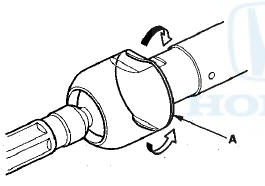
64. Coat the inside surface of the cylinder end (A) with power steering fluid, then install the cylinder end by screwing it into the cylinder (B). Tighten the cylinder end to the specified torque.
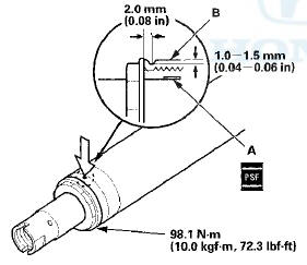
65. Stake the point of the cylinder shown (opposite from where the stake was removed during disassembly).
66. Coat the new O-ring (A) with steering grease, and carefully fit it on the valve housing.
67. Apply steering grease to the ball bearing (B) in the gearbox housing, then install the valve body unit (C) by engaging the gears. Note the valve body unit installation position (direction of the line connections).
68. Loosely install the flange bolts (D).
69. Install cylinder line A and B to the steering gearbox.
Note these items during reassembly: -Thoroughly clean the joints of the cylinder lines.
The joints must be free of foreign material.
-Install the cylinder lines by tightening the flare nuts by hand first, then tighten the flare nuts to the specified torque.
70. Apply steering grease to the sliding surface of the rack guide (A), and install it onto the gearbox housing.
71. Remove the old sealant from the rack guide screw (B), then apply new sealant (Three Bond 1215 or Loctite 5699) to the middle of the threads. Install the spring (C), rack guide screw, and locknut (D).
NOTE: If more than 5 minutes have passed after applying the sealant, remove the old sealant and residue, and reapply new sealant,. .
72. Adjust the rack guide screw (see page 17-17). After adjusting, check that the rack moves smoothly by sliding it right and left.
73. Hold the gearbox housing using a C-clamp (A) and wooden blocks (B) to a work bench as shown. Do not clamp the cylinder part of the gearbox housing in a vise.
74. Install a new rubber stop (A) and a new lock washer (B). Align the lock washer tabs (C) with the slots (D) on the rack end (E) while holding the lock washer in place. Repeat this step for the other side of the rack.
75. Hold the flat surface sections of the steering rack with one wrench, and tighten both rack ends with another wrench. Be careful not to damage the rack surface with the wrench.
76. Bend the lock washer (A) back against the flat spots on the rack end joint housing.
77. Apply multipurpose grease to the circumference of the rack end joint housing (A).
7 8 . Apply d n y n i . uudi uf silicone grease (P/N 08798-9013) to the boot grooves (B) on the rack end.
NOTE: Make sure not to get any silicone grease on the terminal part of the connectors, especially if you have silicone grease on your hands or gloves.
79. Center the steering rack within its stroke.
80. Install the new self-locking nut (A) onto the pinion shaft end, and tighten to the specified torque.
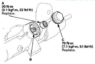
81, Remove the old sealant from the threads on the gearbox housing (B), and apply new sealant (Three Bond 1215 or Loctite 5699) all the way around the threads on the gearbox housing and the new end plug (C). Install the end plug onto the gearbox housing, and tighten it to the specified torque.
NOTE: If more than 5 minutes have passed after applying the sealant, remove the old sealant and residue, and reapply new sealant.
82. Tighten the flange bolts (A) to the specified torque.
83. After tightening, use a drift to stake (A) the gearbox housing shoulder against the end plug (B).
84. Clean off any grease or contamination from the boot installation grooves (A) around the gearbox housing.
Install the boots (B) on the rack ends with the tie-rod clips (C), and fit the boot end in the installation grooves in the housing properly.
85. After installing the boots, wipe the grease off the threaded section (D) of the rack end.
86. Install the new boot bands (A) by aligning the tabs (B) with the holes (C) on the band.
87. Close the ear portion (A) of the boot band (B) with commercially available pincers, Oetiker 1098 or equivalent (C).
88. Slide the rack right and left to be certain that the boots are not deformed or twisted.
89. Install the tie-rod end to the rack end.
90. Install the steering gearbox (see page 17-60).
 Steering Gearbox Removal
Special Tools Required
-Engine Hanger Adapter VSB02C000015*
•Engine Support Hanger, A and Reds
AAR-T1256*
-Ball Joint Remover, 28 mm 07MAC-SL0A202
-Ball Joint Thread Protector, 12 mm
07AA ...
 Steering Gearbox Installation
Special Tools Required
-Subframe Adapter VSB02C000016*
-Subframe Alignment Pin 070AG-SJAA10S
-Engine Support Hanger, A and Reds AAR-T1256*
-Engine Hanger Adapter VSB02C000015*
*: Available throug ...
See also:
MICU Input Test
NOTE:
• Before testing, troubleshoot the multiplex
integrated control unit first, using B-CAN System Diagnosis Test Mode A
(see page 22-134).
• Before testing, make sure the No. 5 (7. ...
System Description
Overview
The audio unit acts as the processor for all audio functions. You can select
the audio functions from the front panel, the
audio remote (on the steering wheel), or by using the navigation ...
Audio/Information Screen
Displays the audio status and wallpaper. From this screen, you can go to
various
setup options.
• Switching the Display
Press the (display) button to
change the display.
• Audio
Shows ...