 Honda Accord: SRS Unit Replacement
Removal
1. Do t h e b a t t e r y t e r m i n a l d i s c o n n e c t i o n procedure (see page 22-91), t h e n w a i t at least 3 m i n u t e s before s t a r t i n g work.
2. Remove t h e d r i v e r ' s a n d passenger's dashboard center l o w e r cover (see page 20-170).
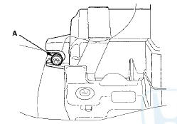
3. Remove t h e TORX bolt (A) u s i n g a TORX T30 bit.
4. Remove t h e a u d i o disc changer ( w i t h navigation system) (see page 23-118) or center pocket (without n a v i g a t i o n system) (see page 20-168).
5. Disconnect SRS u n i t connectors A (39P) a n d B (39P) f r o m t h e SRS unit (C).
NOTE: T h e SRS u n i t connectors have lever locks.
Release t h e locks before d i s c o n n e c t i n g t he connectors (see page 24-30).
6. Remove t h e TORX bolts (D) u s i n g a TORX T30 bit, then pull out the SRS unit.
Installation
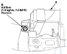
1. Install t h e SRS u n i t (A) w i t h a n e w TORX bolt (B),using a TORX T30 bit.
NOTE: Be s u r e t h e SRS u n i t is s i t t i ng squarely against it's bracket before torquing the TORX bolt.
2. Install t h e n e w TORX bolts (A) u s i n g a TORX T30 b i t t h e n connect t h e connectors (B) t o t h e SRS unit (C); push t h em i n t o p o s i t i on until t h e y click (see page 24-30).
3. Do t he battery terminal reconnection procedure (see page 22-91).
4. Make sure t h e SRS unit has t h e latest software. If it does not have t h e latest, update t h e software in t he SRS unit (see page 24-39).
5. Do t he ODS unit initialization (see page 24-40).
6. Check t he o p e r a t i o n of t h e ODS u n i t w i t h t h e HDS (see page 24-41).
7. C o n f i rm proper SRS o p e r a t i o n : T u r n t h e i g n i t i on switch t o ON (II); t h e SRS indicator s h o u l d c o m e on f o r about 6 seconds and t h e n g o off.
8. Reinstall all removed parts.
 Cable Reel Replacement
Removal
1. Make sure t h e f r o n t w h e e l s are a l i g n e d straight
ahead.
2. Do t h e b a t t e r y t e r m i n a l d i s c o n n e c t i o n procedure
(see
page 22-91), t h e n w a i ...
 Side Impact Sensor (First) Replacement
4-Door
Removal
1. Do t h e battery t e r m i n a l d i s c o n n e c t i o n procedure (see
page 22-91), t h e n w a i t at least 3 m i n u t e s before
s t a r t i ng work.
2. Remove t h e B-p ...
See also:
Countershaft Reassembly
Exploded View
*: The components of the triple cone synchro assembly.
Special Tools Required
-СћDriver Handle, 40 mm I.D. 07746-0030100
- Bearing Driver Attachment, 30 mm 07746-0030300
NOTE: R ...
Countershaft Reverse Selector Hub and
3rd Gear Removal
1. Install a commercially available bearing separator on
4th gear (A). Set the countershaft (B) on a press with a
spacer (C) between the press and the countershaft,
and remove the reverse selector ...