 Honda Accord: MICU Input Test
NOTE: # Before t e s t i n g , t r o u b l e s h o o t the m u l t i p l e x i n t e g r a t e d control unit first, using B-CAN System D i a g n o s i s Test Mode A (see page 22-134).
• Before t e s t i n g , do the gauge c o n t r o l module s e l f - d i a g n o s i s f u n c t i o n (see page 22-332), and make sure the s a f e ty i n d i c a t o r LEDs and B-CAN c o m m u n i c a t i o n line are OK.
Driver's MICU
1. Turn the ignition switch to LOCK (0), and remove the driver's d a s h b o a r d lower cover (see page 20-166).
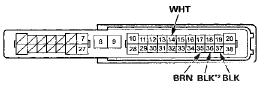
2. D i s c o n n e c t d r i v e r ' s under-dash fuse/relay box c o n n e c t o r s D, Q, and R.
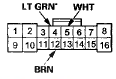
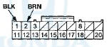
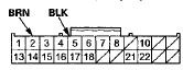
NOTE: All c o n n e c t o r v i e w s are w i r e side of f e m a l e t e r m i n a l s .
CONNECTOR D(16P)
CONNECTOR Q (20P)
CONNECTOR R (24P)
*: 4-door
3. Inspect the connector and socket terminals to be sure they are all making good contact.
• If the terminals are bent, loose or corroded, repair them as necessary and recheck the system.
• If the terminals look OK, go to step 4 .
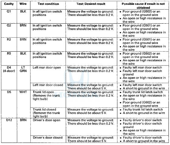
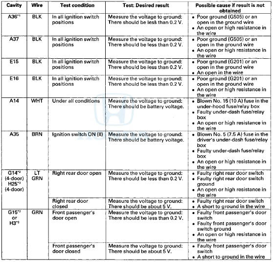
4. Reconnect the connectors to the driver's under-dash fuse/relay box, and do these input tests at the following connector.
• If any test indicates a problem, find and correct the cause, then recheck the system.
• If all the input tests prove OK go to step 5.
Passenger's MICU
5. Turn the ignition switch to LOCK (0), and remove the passenger's kick panel.
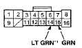
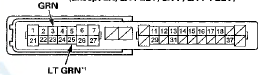
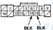
• 2-door (see page 20-105) • 4-door (see page 20-107) 6. Disconnect passenger's under-dash fuse/relay box connectors A, E, and G # 1 (or H*2).
*1: LX, LX PZEV, LX-P, LX-P PZEV
*2: Except LX, LX PZEV, LX-P, LX-P PZEV
NOTE: All connector views are wire side of female terminals.
CONNECTOR A (38P)
CONNECTOR G (16P) (LX, LX PZEV, LX-P, LX-P PZEV)
CONNECTOR H (38P) (Except LX, LX PZEV, LX-P, LX-P PZEV)
CONNECTOR E (18P)
*1: 4-door
*2: '08-09 models
7. Inspect the connector and socket terminals to be sure they are all making good contact.
• If the terminals are bent, loose or corroded, repair them as necessary and recheck the system.
• If the terminals look OK, go to step 8.
8. Reconnect the connectors to the passenger's under-dash fuse/relay box, and do these input tests at the following connectors.
• If any test indicates a problem, find and correct the cause, then recheck the system.
• If all the input tests prove OK, go to step 9.
*1:'08-09 models
*2: LX, LX PZEV, LX-P, LX-P PZEV
*3: Except LX, LX PZEV, LX-P, LX-P PZEV
9. If multiple failures are found on more than one control unit, replace the driver's under-dash fuse/relay box (includes the driver's MICU).
• USA models (see page 22-86) • Canada models (see page 22-87) If input failures are related to a particular control unit, replace the control unit
 Circuit Diagram
...
 Reminder Systems
...
See also:
Security Hood Switch Test
1. Open the hood.
2. Disconnect the 2P connector from the security hood
switch.
3. Check for continuity between the terminals.
• There should be continuity between terminals No. 1
and ...
System Description
Delay Orifice Mechanism
Function
The delay orifice mechanism improves clutch operation by delaying the slave
cylinder release speed when the clutch
pedal is suddenly released. The delay orifice m ...
Steering Column Inspection
Inspection
1. Remove the steering column (see page 17-10).
2. Check these items;
•Check for loose bearing mounting nuts (A).
If they are loose, replace the column as an assembly.
-Check ...