 Honda Accord: Knuckle/Hub Bearing Unit Replacement
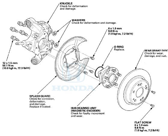
Exploded View
Special Tools Required
- Ball Joint Thread Protector, 14 mm 07AAE-SJAA100
- Ball Joint Remover, 32 mm 07MAC-SL0A102
Hub Bearing Unit Replacement
1. Raise and support the vehicle (see page 1-13).
2. Remove the wheel nuts, and the rear wheel.
3. Release the parking brake lever fully.
4. Loosen the parking brake cable adjusting nut (see page 19-8).
5. Remove the flange bolt (A) from the arm (B). Then disconnect the parking brake cable from the lever (C).
6 Remove the brake hose mounting bolt (A).
7. Remove the brake caliper bracket mounting bolts (B), then remove the caliper assembly (C) from the knuckle. To prevent damage to the caliper assembly or the brake hose, use a short piece of wire to hang the caliper assembly from the undercarriage. Do not twist the brake hose excessively.
8. Remove the two washers (A).
NOTE: During installation, make sure the washers are installed between the brake caliper bracket and the knuckle.
9. Remove the rear brake disc (see page 19-34).
10. Remove the hub bearing unit (A) and the O-ring (B).
11. Check the hub bearing unit for damage and cracks, 12. install the hub bearing unit in the reverse order of removal, and note these items: - Use a new O-ring on reassembly.
- After installing the brake caliper, make sure the clearance between lower arm B and the parking brake cable is more than 5 mm (0.2 in).
- Before installing the brake disc, clean the mating surfaces of the hub bearing unit and the brake disc.
- Before installing the wheel, clean the mating surfaces of the brake disc and the inside of the wheel.
13. Check the wheel alignment, and adjust it if necessary (see page 18-5).
Knuckle Replacement
1. Remove the hub bearing unit.
2. Remove the splash guard (A).
3. Remove the lock pin (A) from the upper arm ball joint, then remove the castle nut (B).
NOTE: During installation, install the lock pin as shown after tightening the new castle nut.
4. Disconnect the upper arm ball joint from the knuckle using the ball joint thread protector and the ball joint remover (see page 18-10).
NOTE: - Be careful not to damage the ball joint boot when installing the remover.
- During installation, to connect the ball joint, raise the suspension with a jack (see step 9 on page 18-44).
5. Remove the wheel speed sensor (A) from the knuckle.
Do not disconnect the wheel speed sensor connector.
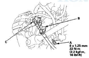
6. Remove the flange nut (A) while holding the joint pin (B) with a hex wrench (C), then disconnect the stabilizer link (D) from the knuckle, and remove the brake hose bracket (E).
NOTE: Use the new flange nut during reassembly.
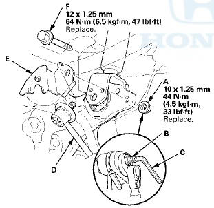
7. Remove the damper lower mounting bolt (F).
NOTE: Use the new mounting bolt during reassembly.
8. Remove the control arm mounting self-locking nut (A) and the washer (B).
NOTE* Use a new self-locking nut during reassembly.
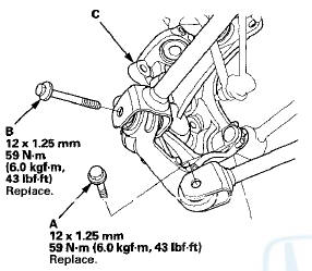
9. Remove the lower arm mounting bolt (A), and the lower arm B mounting bolt (B), then remove the knuckle (C).
NOTE: Use new mounting bolts during reassembly.
10. Install the knuckle in the reverse order of removal, and note these items: - First install all of the components, and lightly tighten the bolts and the nuts, then raise the suspension to load it with the vehicle's weight before fully tightening to the specified torque.
- Be careful not to damage the ball joint boot when connecting the knuckle.
- Before connecting the ball joint, degrease the threaded section and the tapered portion of the ball joint pin, the ball joint connecting hole, and the threaded section and the mating surfaces of the castle nut.
- Torque the castle nut to the lower torque specification, then tighten it only far enough to align the slot with the ball joint pin hole. Do not align the castle nut by loosening it.
- Before installing the wheel, clean the mating surfaces on the brake disc and the inside of the wheel.
11. Check the wheel alignment, and adjust it if necessary (see page 18-5).
 Rear Suspension
...
 Upper Arm Replacement
Special Tools Required
- Ball Joint Thread Protector, 14 mm 07AAE-SJAA100
* Ball Joint Remover, 32 mm 07MAC-SL0A102
1. Raise and support the vehicle (see page 1-13).
2. Remove the rear wheel.
...
See also:
Dashboard/Steering Hanger Beam
Disassembly/Reassembly
Special Tools Required
KTC Trim Tool Set SOJATP2014*
*Available through the Honda Tool and
Equipment
Program; call 888-424-6857
NOTE:
- Put on gloves to protect your hands.
В© Take care no ...
ECT Sensor 2 Replacement
1. Remove the front splash shield, (see page 20-291)
2. Drain the engine coolant (see page 10-6).
3. Disconnect the ECT sensor 2 connector (A), then
remove ECT sensor 2 (B).
4. Install ECT sen ...
DTC Troubleshooting
DTC U0155: Immobilizer-keyless Control Unit
Lost Communication With Gauge Control
Module
NOTE: If you are troubleshooting multiple DTCs, be sure
to follow the instructions in B-CAN System Diagnosi ...