 Honda Accord: Heater Unit/Core Replacement
SRS components are located in this area. Review the SRS component locations (see page 24-21) and the precautions and procedures (see page 24-25) before doing repairs or service.
1. Do the battery terminal disconnection procedure (see page 22-91).
2. Recover the refrigerant with a recovery/recycling/ charging station (see page 21-80).
3. Disconnect the A/C line from the evaporator core (see page 21-67).
4. When the engine is cool, drain the engine coolant from the radiator (see page 10-6).
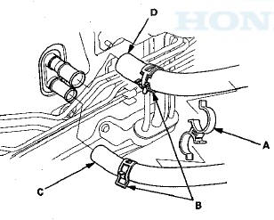
5. From under the hood, remove the clamp (A). Slide the hose clamps (B) back. Disconnect the inlet heater hose (C) and the outlet heater hose (D) from the heater unit. Note the layout of the hoses.
Engine coolant will run out when the hoses are disconnected; drain it into a clean drip pan. Be sure not to let coolant spill on the electrical parts or the painted surfaces. If any coolant spills, rinse it off immediately.
6. Remove the mounting nut from the heater unit. Take care not to damage or bend the fuel lines or brake lines, etc.
7. Remove the dashboard (see page 20-183).
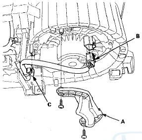
8. Disconnect the connector (A). Remove the clips (B), ducts (C), and the drain hose (D). Then remove the mounting bolt, the mounting nuts, and the blower-heater unit (E).
9. Remove the two screws, then remove the cover (A).
10. Disconnect the connector (B) from the blower motor.
Remove the wire harness clip (C).
11. Disconnect these connectors (A): The mode control motor, the power transistor, the evaporator temperature sensor, the passenger's air mix control motor (with climate control), and the recirculation control motor. Remove the wire harness clips (B).
12. Disconnect the connector (A) from the air mix control motor. Remove the wire harness clips (B), the connector clip (C), and the wire harness (D).
13. Remove the self-tapping screws and the passenger's heater duct (A). Remove the self-tapping screws and the expansion valve cover (B). Remove the self-tapping screw and the heater core cover (C).
Remove the self-tapping screws, the heater pipe bracket (D), and the grommet (E), and carefully pull out the heater core (F).
14. Install the heater core and the evaporator core in the reverse order of removal.
15. Install the heater unit in the reverse order of removal, and note these items: В© Do not interchange the inlet and outlet heater hoses, and install the hose clamps securely.
• Refill the cooling system with engine coolant (see page 10-6).
• Make sure that there is no coolant leakage.
• Make sure that there is no air leakage.
16. Do the battery terminal reconnection procedure (see page 22-91).
 Expansion Valve Replacement
1. Remove the evaporator core (see page 21-67).
2. Remove the insulator (A) and bolts, then remove the
expansion valve (B) and O-rings (C).
3. Install the expansion valve in the reverse order o ...
 A/C Compressor Replacement
NOTE: Do not install the A/C compressor into a system
unless you are completely sure that the system is free of
contamination. Installing the A/C compressor into a
contaminated system can result in ...
See also:
Intermediate Shaft Removal
1. Drain the transmission fluid. Reinstall the drain plug
using a new sealing washer:
-Manual transmission (see page 13-5)
-Automatic transmission (see page 14-192)
2. Remove the right driveshaft ...
Important Safety Precautions
Refer to the safety information that
came with your garage door opener
to test that the safety features are
functioning properly. If you do not
have this information, contact the
manufacture ...
DTC Troubleshooting
DTC P0461: Fuel Level Sensor (Fuel Gauge
Sending Unit) Circuit Range/Performance
Problem
NOTE:
- Before you troubleshoot record all freeze data and
any on-board snapshot, and review the general
...