 Honda Accord: General Troubleshooting Information
How to Use the Self-diagnostic Function
The HVAC control unit has a self-diagnostic function for the heating, ventilation, and air conditioning system. To run the self-diagnostic function, do the following: 1. Turn the ignition switch to LOCK (0), and then to ON (li).
2. Set the FAN CONTROL dial to OFF, the TEMPERATURE CONTROL dial on Max Cool, and select the VENT mode.
3. Turn the ignition switch to LOCK (0), and then to ON (II).
4. Press and hold the RECIRCULATION CONTROL button, then within 10 seconds press and release the REAR WINDOW DEFOGGER/MIRROR DEFOGGER button five times. Release the RECIRCULATION CONTROL button; the recirculation indicator blinks two times, then the self-diagnostic begins.
NOTE: • The blower motor will run at various speeds when in the self-diagnostic mode.
• Once the self-diagnostic function is finished, the recirculation indicator blinks, and the number of blinks indicates the Diagnostic Trouble Code (DTC) number. If there are multiple DTCs, the indicator blinks each DTC in sequence from the lowest DTC number to the highest.
• The indicator pauses 3 seconds, then repeats the DTC blink sequence.
• If no DTCs are found, the indicator does not blink.
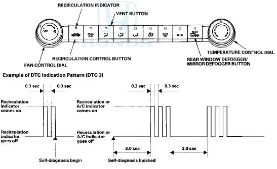
Example of DTCs Indication Pattern {DTC 2 and 41
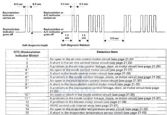
*1: '08-10 models with M/T and '08-09 models 2-door with A/T
*2: '08-09 models 4-door with A/T and '10 model with A/T
Clear the DTCs
When the problem is repaired, DTCs will automatically clear.
Max Cool Position Function
When the mode control button is in the MAX A/C position, the HVAC control unit will automatically select the recirculation mode and turn the A/C on. If the recirculation switch is pressed when in MAX A/C mode, MAX A/C turns off.
If the A/C switch is pressed when in MAX A/C mode, the A/C turns off.
 A/C System Inspection
Before troubleshooting any problem with the air
conditioning system, do the following:
1. With the ignition switch in LOCK (0), inspect the A/C
components, the pressure lines and the hoses for
sta ...

See also:
Engine Coolant
Adding Engine Coolant
If the coolant level in the reserve
tank is at or below the MIN line, add
coolant to bring it up to the MAX line.
Inspect the cooling system for leaks.
Always use Hond ...
CMP Pulse Plate B Replacement
1. Remove the cylinder head cover (see page 6-73).
2. Remove camshaft position (CMP) sensor B (see page
11-198).
3. Hold the camshaft with an open-end wrench, then
loosen the bolt.
4. Remov ...
Important Maintenance Precautions
If you have the required service
done but do not reset the display, or
reset the display without doing the
service, the system will not show the
correct maintenance intervals. This
can lead ...