 Honda Accord: Front Accessory Power Socket
Test/Replacement
Honda Accord: Front Accessory Power Socket
Test/Replacement
NOTE: If all of the front and console accessory power sockets do not work, check the No. 18 (7.5: A> fuse in the driver's under-dash fuse/relay box and ground (G503) first.
1. Remove the center console panel (see page 20-157).
2. Disconnect the 2P connector (A) from the front accessory power socket (B).
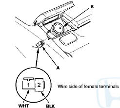
3. Inspect the connector terminals to be sure they are all making good contact.
• If the terminals are bent, loose, or corroded, repair them as'necessary and recheck the system.
• If the terminals look OK, goto step 4.
4. Turn the ignition switch to ACCESSORY (I).
5. Measure the voltage between driver's under-dash fuse/relay box connector D (16P) terminal No. 14 and body ground. There should be less than 0.2 V.
• If there is less than 0.2 V, go to step 6. • If there is more than 0.2 V, check for: - An open or high resistance in the wire between driver's under-dash fuse/relay box connector D (16P) terminal No.'14 and ground (G601).
-Poor ground. (G601).
6. Measure the voltage between front accessory power socket 2P connector terminal No. 1 and body ground.
There should be battery voltage.
• If there is battery voltage, go to step 7.
• If there is no voltage, check for: - A blown No. 23 (15 A) fuse in the driver's under-dash fuse/relay box.
- A faulty front accessory power socket relay - An open or high resistance in the wire between driver's under-dash fuse/relay box connector P (20P) terminal No. 1 and cigarette lighter 2P connector terminal No. 1.
7. Check for continuity between the front accessory power socket terminal. No. 2 and body ground. There should be continuity.
• If there is continuity, replace the power socket; go to step 8.
• If there is no continuity, check for: - Poor ground (G503).
- An open or high resistance in the wire between front accessory power socket 2P connector terminal No. 2 and body ground (G503).
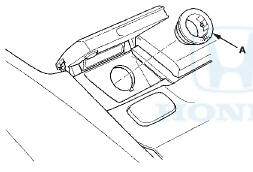
8. Remove the socket (A).
9. Remove the housing (A) f r om the panel.
10. Install the power socket in the reverse order of removal.
 Circuit Diagram
...
 Console Accessory Power Socket
Test/Replacement
Console Accessory Power Socket
Test/Replacement
NOTE: If all of the front and console accessory power
sockets do not work, check the No. 1 8 (7.5 A) fuse in the
driver's under-dash fuse/relay box and ground (G503)
first.
1. Remove the center ...
See also:
Mainshaft 5th Gear Axial Clearance
Inspection
1. Remove the mainshaft transmission housing bearing
(seepage 14-270).
2. Install the thrust needle bearing ( A ) , 5th gear ( B ) , the
needle bearing (C), the thrust needle bearing (D), the
41 ...
End Cover Removal
Special Tools Required
Mainshaft Holder 07GAB-PF50101
1. Remove the three bolts (D) securing the ATF cooler inlet line brackets,
the ATF filter bracket bolts (E), the ATF cooler
line banjo bolts ...
Important Safety Precautions
Refer to the safety information that
came with your garage door opener
to test that the safety features are
functioning properly. If you do not
have this information, contact the
manufacture ...