 Honda Accord: Engine Removal
Special Tools Required
. Universal Lifting Eyelet 07AAK-SNAA120
Engine Hanger Adapter VSB02C000015*
- Engine Support Hanger, A and Reds AAR-T1256*
- Subframe Adapter VSB02C000016*
*Available through the Honda Tool and
Equipment Program, 888-424-6857
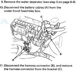
NOTE:
Р’В© Use fender covers to avoid damaging painted surfaces.
- To avoid damaging the wiring and terminals, unplug the wiring connectors carefully while holding the connector portion.
- Mark all wiring and hoses to avoid misconnection.
Also, be sure that they do not contact other wiring or hoses, or interfere with other parts.
1. Remove the hood support rod, then use it as shown to prop the hood in the wide-open position.

2. Remove the front grille cover:
- 2-door (see page 20-274)
4-door (see page 20-274)
3. Remove the strut brace (if equipped) (see page 20-306).
4. Relieve the fuel pressure (see page 11-306).
5. Do the battery removal procedure (see page 22-92).
6. Remove the intake air duct (see step 2 on page 10-12).
7. Remove the air cleaner assembly (see page 11-332).
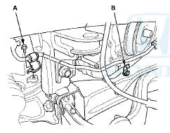
8. Remove the harness clamps (A), then remove the battery base (B).

Engine Removal (cont'd)
12. Remove the engine control module (ECM)/powertrain control module (PCM) cover (A), then remove the three bolts (B) securing the ECM/PCM.

13. Disconnect the ECM/PCM connectors (A) and the engine wire harness connector (B).
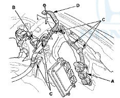
14. Remove the harness clamps (C) and the bracket (D).
15. Disconnect the evaporative emission (EVAP) canister hose (A) and the brake booster vacuum hose (B).

16. Remove the quick-connect fitting cover (A), then disconnect the fuel feed hose (B) (see page 11-314).
17. Remove the drive belt (see page 4-30).
18. Remove the power steering (P/S) pump (A) without disconnecting the P/S hoses, and the P/S hose bracket (B).

19. Wait until the engine is cool, then carefully remove the radiator cap.
20. Remove the A/C condenser fan shroud assembly (see page 10-13).
21. M/T model: Remove the three bolts securing the shift cable holder, then remove the shift cable and the select cable. Do not bend the cables excessively.
22. M/T model: Remove the clutch slave cylinder and the clutch line bracket mounting nut. Do not operate the clutch pedal once the slave cylinder has been removed (see step 6 on page 13-7).
23. Raise the vehicle on the lift.
24. Remove the front wheels.
25. Remove the splash shield.
26. Loosen the drain plug in the radiator, and drain the engine coolant (see page 10-6).
27. Drain the engine oil (see page 8-11).
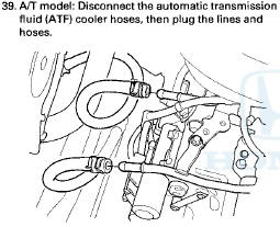
28. Drain the transmission fluid: - Manual transmission (see page 13-5) - Automatic transmission (see page 14-192) 29. Remove exhaust pipe A.
30. A/T model: Remove the shift cable. Do not bend the shift cable excessively: - Vehicles with JHM VINs (see step 46 on page 14-200).
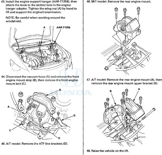
- Vehicles with 1HG VINs (see step 48 on page 14-200).
31. Remove the damper fork (see page 18-31).
32. Separate the knuckles from the lower arms (see step 11 on page 18-15).
33. Remove the driveshafts (see page 16-4). Coat all precision-finished surfaces with new engine oil. Tie a plastic bag over the driveshaft ends.
34. Remove the bolt (A) securing the P/S fluid line bracket and unclamp the P/S fluid line clamp (B) on the front subframe.
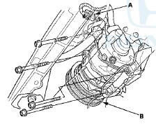
35. Remove the bolts securing the steering gearbox mounting bracket (A) and the heat shield (B). (right side)

38. Remove the bolts securing the steering gearbox stiffeners (A) and the washers (B). (left side)

40. Disconnect the heater hoses (A) and the upper radiator hose (B).


49. Remove the nuts securing the lower transmission mount.

50. Disconnect the A/C compressor clutch connector (A), then remove the A/C compressor (B) without disconnecting the A/C hoses. Do not bend the A/C hoses excessively.
51. Remove the subframe middle mounts.
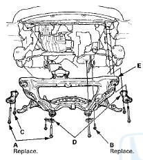
52. Attach the subframe adapter (VSB02C000016) to the subframe by looping the belt (A) over the front subframe (B), then secure the belt with its stop (C).
53. Raise the jack and line up the slots in the subframe adapter arms with the bolt holes on the jack base, then securely attach them with four bolts.
54. Remove the front subframe mounting bolts (A), the four 12 x 1.25 mm bolts (B),(C) securing four stiffeners (D), then lower the front subframe (E).
55. Lower the vehicle on the lift.
56. Remove the ground cable (A).
57. Remove the side engine mount bracket (B).
58. Install the universal lifting eyelet (07AAK-SNAA120).

59. Attach a chain hoist (A) to the universal lifting eyelet (B) and the transmission hook (C), then lift the engine/ transmission until it is securely supported by the chain hoist, and remove the engine support hanger.
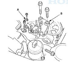
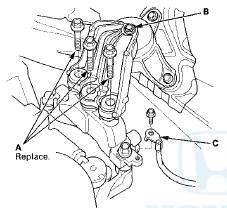
60. Remove the upper transmission mount bracket mounting bolts (A).
NOTE: Do not remove the TORX bolt (B) from the upper transmission mount. If the TORX bolt is removed, the upper transmission mount must be replaced as an assembly.
M/T mode
A/T model
61. Remove the ground cable (C).
62. Check that the engine/transmission is completely free of the vacuum hoses, the fuel hoses, the coolant hoses, and the electrical wiring.
63. Slowly lower the engine/transmission about 150 mm (6 in). Check once again that all the hoses and the electrical wiring are disconnected and free from the engine/transmission, then lower it all the way.
64. Disconnect the chain hoist from the engine/ transmission.
65. Raise the vehicle, and remove the engine/transmission from under the vehicle.
 Special Tools
...
 Engine Installation
Special Tools Required
- Universal Lifting Eyelet 07AAK-SNAA120
Engine Hanger Adapter VSB02C000015
Engine Support Hanger, A and Reds AAR-T-1256*
Subframe Adapter VSB02C000016
Subframe Alignment P ...
See also:
Exterior Care
Dust off the vehicle body after you drive.
Regularly inspect your vehicle for scratches on painted surfaces. A scratch on a
painted surface can result in body rust. If you find a scratch, promptly ...
Regulator Valve Body Disassembly,
Inspection, and Reassembly
1. Clean all parts thoroughly in solvent and dry them with compressed air.
Blow out all passages.
2. Inspect the valve body for scoring and damage.
3. Check all valves for free movement. If an ...
Playing an MP3/WMA Disc
The changer plays MP3/WMA files
in recorded order. Each disc can
hold up to 400 playable files within 8
folder layers. When playing MP3
discs, a disc can support a maximum
number of 100 fold ...