 Honda Accord: Engine Installation
Special Tools Required
- Universal Lifting Eyelet 07AAK-SNAA120
Engine Hanger Adapter VSB02C000015
Engine Support Hanger, A and Reds AAR-T-1256*
Subframe Adapter VSB02C000016
Subframe Alignment Pin 070AG-SJAA10S
Available through the Honda Tool and Equipment Program, 888-424-6857
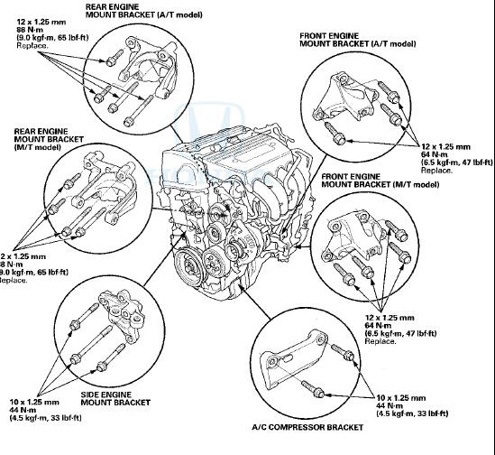
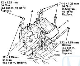
1. Install the engine mount brackets and the accessory brackets, and tighten their bolts to the specified torque.
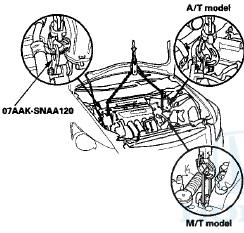
2. Raise the vehicle on the lift, and position the engine/ transmission under the vehicle. Lower the vehicle, and attach the universal lifting eyelet (07AAK-SNAA120) and the chain hoist to the universal lifting eyelet and the transmission hook, then lift the engine into position in the vehicle.
NOTE: Reinstall the mounting bolts and the support nuts in the sequence given in the following steps.
Failure to follow this sequence may cause excessive noise and vibration, and reduce engine mount life.
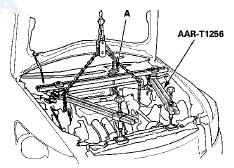
3. Attach the engine hanger adapter (VSB02C000015) to the threaded hole in the cylinder head.

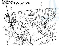
4. Install the engine support hanger (AAR-T1256), then attach the hook to the slotted hole in the engine hanger adapter. Tighten the wing nut (A) by hand to lift and support the engine/transmission.
NOTE: Be careful when working around the windshield.
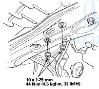
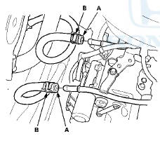
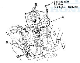
5. Tighten the new upper transmission mount bracket mounting bolts (A) to the specified torque.
M/T model
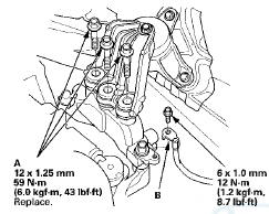
6. Install the ground cable (B).
7. Remove the chain hoist.
8. Remove the universal lifting eyelet.
9. Install the side engine mount bracket (A), then tighten the new side engine mount bracket mounting bolts (B).
10. Install the ground cable (C).
11. Raise the vehicle on the lift.
12. Spport the front subframe (A) with the subframe adapter (VSB02C000016) and a jack, raise the front subframe up to the body.
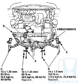
13. Loosely install the new front subframe mounting bolts (four) (B), the 12 x 1.25 mm bolts (four) (C) (D), and the stiffeners (four) (E).
14. Install the subframe middle mount (A), then loosely tighten the new subfrme middle mount mounting bolts (B).
15. Remove the jack and the subframe adapter.
16. Insert the subframe alignment pin (070AG-SJAA1 OS) through the positioning slot (A) on the right rear stiffener, through the positioning hole (B) on the subframe, and into the positioning hole (C) on the body, then loosely tighten the subframe right rear mounting bolt.
17. Insert the subframe alignment pin through the positioning slot on the left rear stiffener, through the positioning hole on the subframe, and into the positioning hole on the body, then loosely tighten the subframe left rear mounting bolt.
18. With the subframe alignment pin in place, tighten the subframe right rear mounting bolt.
19. With the subframe alignment pin in place, tighten the subframe left rear mounting bolt.
20. Tighten the stiffener mounting bolts to the specified torque.
21. Tighten the front and rear subframe mounting bolts to the specified torque.
22. Check that the positioning slots on the right/left rear stiffener, the positioning holes on the subframe, and the positioning holes on the body are aligned using the subframe alignment pin.
23. Tighten the bolts securing the subframe middle mounts.
24. Tighten the nuts securing the lower transmission mount.
25. Lower the vehicle on the lift.
26. Remove the engine support hanger and the engine hanger adapter.
27. Tighten the new front engine mount bolt (A), then install the front engine mount stop (B) and connect the vacuum hose (C).
28. A/T model: Install the automatic transmission fluid (ATF) cooler line brackets (D).
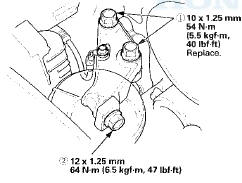
29. M/T model: Install the rear engine mount (A),then tighten the new rear engine mount mounting bolts in the numbered sequence shown.

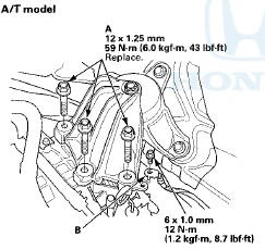
30. A/T model: Install the rear engine mount upper bracket (A). Install the rear engine mount (B), then tighten the new rear engine mount mounting bolts in the numbered sequence shown.
31 Loosen the mounting bolts for the side engine mount bracket, then retighten the bolts in the numbered sequence shown.
32. Loosen the mounting bolts for the upper transmission mount bracket, then retighten them to the specified torque.
M/T model
A/T model
33. Connect the quick connector to the thermostat cover (see step 11 on page 10-8).
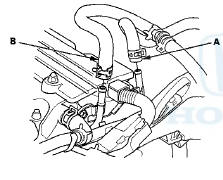
34. Connect the heater hoses (A) and the upper radiator hose (B).
35. A/T model; Connect the ATF cooler hoses (A), and secure the hoses with the clips (B) (see page 14-220).
36. Install the bolts securing the steering gearbox stiffeners (A) and the washers (B). (left side)
10 x 1.25 mm
59 N-m (6.0 kgf-m, 43 ibf-ft)
37. Install the two bolts (A) securing the power steering (P/S) fluid line brackets.
38. Raise the vehicle on the lift.
39. Install the bolts securing the steering gearbox mounting bracket (A) and the heat shield (B). (right side)
40. Install the P/S fluid line bracket (A)r and secure the hose with the hose clamp (B).
41. Install the A/C compressor (A), then connect the A/C compressor clutch connector (B).
42. Install a new set ring on the end of each driveshaft, then install the driveshafts (see page 16-19). Make sure each ring "clicks" into place in the differential and the intermediate shaft.
43. Connect the lower arms to the knuckles (see step 5 on page 18-21).
44. Install the damper fork (see step 3 on page 18-21).
45. A/T model: install the shift cable. Do not bend the shift cable excessively: - Vehicles with JHM VINs (see step 33 on page 14-209).
- Vehicles with 1HG VINs (see step 36 on page 14-210).
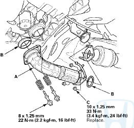
46. Install exhaust pipe A using new gaskets (B) and new self-locking nuts (C).
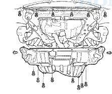
47. Install the splash shield.
48. Install the front wheels.
49. Lower the vehicle on the lift.
50. M/T model: Install the clutch slave cylinder and the clutch line bracket mounting nut (see step 49 on page 13-23).
51. M/T model: Install the shift cable and the select cable, then tighten the three bolts securing the shift cable holder. Do not bend the cables excessively (see step 47 on page 13-22).
52. Install the A/C condenser fan shroud assembly (see page 10-15).
53. Install the P/S pump (A), and the P/S hose bracket (B).
54. Install the drive belt (see page 4-30).
55. Connect the fuel feed hose (A) (see page 11-316), then install the quick-connect fitting cover (B).
56. Connect the evaporative emission (EVAP) canister hose (A) and the brake booster vacuum hose (B).
57. Connect the engine control module (ECM)/powertrain control module (PCM) connectors (A) and the engine wire harness connector (B)
58. Install the harness clamps (C) and the bracket (D).
59. Install the ECM/PCM (A), then install the ECM/PCM cover (B).

80. Connect the battery cables (A) to the under-hood fuse/ relay box.
61. Connect the harness connector (B), and Install the harness connector to the bracket (C).
62. Install the water separator (see step 10 on page 9-8).
63. Install the battery base (A), then install the harness clamps (B).
64. Install the air cleaner assembly (see page 11-332).
65. Install the intake air duct (see step 2 on page 10-12).
66. Install the strut brace (if equipped) (see page 20-306).
67. install the front grille cover:
- 2-door (see page 20-274)
- 4-door (see page 20-274)
68. Do the battery installation procedure (see page 22-92).
69. Inspect for fuel leaks. Turn the ignition switch to ON (II) (do not operate the starter) so the fuel pump runs for about 2 seconds and pressurizes the fuel line.
Repeat this operation three times, then check for fuel leakage at any point in the fuel line.
70. Refill the engine with the recommended engine oil (see page 8-11).
71. Refill the transmission with fluid: - Manual transmission (see page 13-5) - Automatic transmission (see page 14-192) 72. A/T model: Move the shift lever to each gear, and verify that the A/T gear position indicator follows the transmission range switch.
73. M/T model: Check that the transmission shifts into all gears smoothly.
74. Refill the radiator with engine coolant, and bleed the air from the cooling system (see step 5 on page 10-6).
75. Do the ECM/PCM reset procedure (see page 11-4).
76. Do the ECM/PCM idle learn procedure (see page 11-293).
77. Do the crankshaft position (CKP) pattern clear/CKP pattern learn procedure (see page 11-5).
78. Inspect the idle speed (see page 11-292).
79. Inspect the ignition timing (see page 4-19).
80. Check the wheel alignment (see page 18-5).
 Engine Removal
Special Tools Required
. Universal Lifting Eyelet 07AAK-SNAA120
Engine Hanger Adapter VSB02C000015*
- Engine Support Hanger, A and Reds AAR-T1256*
- Subframe Adapter VSB02C000016*
*Available thro ...

See also:
Engine Oil Additives
Your vehicle does not require any oil
additives. Additives may adversely
affect the engine or transmission
performance and durability. ...
Front Passenger's Weight Sensor Output Check After
a Vehicle Collision
1. Position the front passenger's seat to the rear most
position, and adjust the seat-back to the forward most
position. Do not move the seat from this position.
2. Drive the vehicle, accelerate ...
Display Setup
You can change the brightness or color theme of the audio/information screen.
• Changing the Screen Brightness
1. Press the SETTINGS button.
2. Rotate to select System
Settings, then
pres ...