 Honda Accord: Electrical Compass Unit Input
Test
Honda Accord: Electrical Compass Unit Input
Test
1. Remove the rear shelf (see page 20-128).
2. Loosen the bolts (A), then pull out the electrical compass unit bracket (B).

3. Disconnect the 6P connector (C) and remove the mounting bolt ( D ) , then pull out the electrical compass unit (E).
4. Inspect the connector and socket terminals to make sure they are all making good contact.
• If the terminals are bent, loose, or corroded, repair them as necessary, and recheck the system.
• If the terminals look OK, go to step 5.
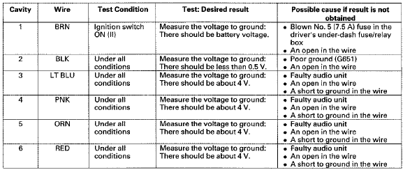
5. Reconnect the electrical compass unit BP connector. Turn the ignition switch to ON (ll), and do the following input tests at the connectors.
• If any test indicates a problem, find and correct the cause, then recheck t h e system.
• If all input t e s t s p r o v e OK, t h e electrical compass unit is faulty; replace it, and do the compass calibration (see page 23-247).
 Electrical Compass Zone Selection
and Calibration
Electrical Compass Zone Selection
and Calibration
NOTE:
• You should do this procedure any time the electrical
compass unit is replaced.
• You should do this procedure in an open area away
from buildings, power lines, and other vehicl ...

See also:
Driver's Airbag Replacement
NOTE: If replacing the driver's airbag after deployment,
refer to Component Replacement/Inspection After
Deployment (see page 24-208) for a complete list of.
other parts that must also be replace ...
Inspection
Out of Vehicle
For front seat belt retractors with seat belt tensioners,
review the SRS component locations, 2-door (see page
24-23), 4-door (see page 24-21) and the precautions and
procedures (se ...
Trunk Lid Release Actuator Test
With Keyless Entry
1. Open the trunk lid.
2. Disconnect 3P connector f r om the trunk lid latch
switch/trunk release actuator.
3. Check actuator operation by connecting power to
terminal No. ...