 Honda Accord: DTC Troubleshooting
DTC indicator A:
Climate Control Unit Internal Error
NOTE: Check the battery condition (see page 22-90) and the charging system (see page 4-25).
1. Turn the ignition switch to LOCK (0), and then to ON (II).
2. Do the self-diagnostic function with the climate control unit (see page 21-103).
3. Check for DTCs.
Is DTC A indicated? YES
-The climate control unit is faulty; replace the climate control unit (with navigation) (see page 21- 190), (without navigation) (see page 21-191).
NO
-lntermittent failure, the climate control unit is OK at this time. Check for poor connections at the climate control unit and at G401 (with navigation) (see page 22- 40), (without navigation) (see page 22-42).
DTC U0155:
Climate Control Unit Lost Communication with Gauge Control Module
NOTE: If you are troubleshooting multiple DTCs, be sure to follow the instructions in B-CAN system diagnosis test mode A (see page 22-134).
1. Clear the DTC with the HDS.
2. Turn the ignition switch to LOCK (0), and then to ON (II).
3. Do the self-diagnostic function with the HDS (see page 21-102).
4. Check for DTCs.
Is DTC U0155 indicated? YES
-Go to step 5.
NO
-The system is OK at this time. Check for loose wires or poor connections at the gauge control module and the climate control unit.
5. Select UNIT INFORMATION in the BODY ELECTRICAL menu.
6. Select CONNECTED UNIT in the UNIT INFORMATION menu.
is the gauge control module detected? YES
-Substitute a known-good climate control unit, and recheck. If the symptom/indication goes away, replace the original climate control unit (with navigation) (see page 21-190), (without navigation) (see page21-191).
NO
-Go to step 7.
7. Disconnect driver's under-dash fuse/relay box connector P (20P).
8. Disconnect the gauge control module 32P connector.
9. Disconnect climate control unit connector B (12P).
10. Check for continuity between the following terminals of driver's under-dash fuse/relay box connector P (20P), the gauge control module 32P connector, and climate control unit connector B (12P).
20P: 32P:
No. 5 No. 18
No. 6 No. 19
12P: 32P:
No. 1 No. 19
No. 2 No. 18
DRIVER'S UNDER-DASH FUSE/RELAY BOX CONNECTOR P (20P)
Wire side of female terminals
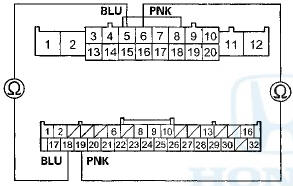
GAUGE CONTROL MODULE 32P CONNECTOR
Wire side of female terminals
GAUGE CONTROL MODULE 32P CONNECTOR
Wire side of female terminals
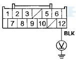
CLIMATE CONTROL UNIT CONNECTOR B (12P)
Wire side of female terminals
Is there continuity? YES
-Go to the gauge control module input test (see page 22-347).
NO
-Repair an open in the wire between the MICU and the gauge control module, or an open in the wire between the climate control unit and the gauge control module.
DTC B121A or DTC indicator G and A /C ON;
An Open in the Mode Control Motor Circuit
1. Clear the DTC with the HDS.
2. Turn the ignition switch to LOCK (0), and then to ON (II).
3. Do the self-diagnostic function with the HDS (see page 21-102) or with the climate control unit (see page 21-103).
4. Check for DTCs.
Is DTC B121A or G and A/C ON indicated? YES
-Go to step 5.
NO
-lntermittent failure. Check for loose wires or poor connections on the mode control motor circuit.
5. Turn the ignition switch to LOCK (0).
6. Test the mode control motor (see page 21-188).
Is the mode control motor OK? YES
-Go to step 7.
NO-
Replace the mode control motor (see page 21-62).
7 Disconnect the mode control motor 7P connector.
8. Disconnect climate control unit connectors A ('MP) andB(12P).
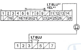
9. Check for continuity between the following terminals of climate control unit connectors A (28P), B (12P), and the recirculation control motor 7P connector.
28P: 7P:
No. 11 No. 3
12P: 7P:
No. 10 No. 7
No. 12 No. 5
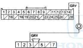
CLIMATE CONTROL UNIT CONNECTOR A (28P)
Wire side of female terminals
MODE CONTROL MOTOR 7P CONNECTOR
Wire side of female terminals
*1: With navigation
*2: Without navigation
CLIMATE CONTROL UNIT CONNECTOR B (12P)
Wire side of female terminals
MODE CONTROL MOTOR 7P CONNECTOR
Wire side of female terminals
*1: With navigation
*2: Without navigation
Is there continuity? YES
-Check for loose wires or poor connections at climate control unit connectors A (28P), B (12P), and at t h e mode control motor IP connector. If the connections are good, substitute a known-good climate control unit and recheck. If the symptom/indication goes away, replace the original climate control unit (with navigation) (see page 21-190), (without navigation) (see page 21-191).
NO
-Repair an open in the wire(s) between the climate control unit and the mode control motor.
DTC B121B or DTC indicator H and A /C ON:
A Short in the Mode Control Motor Circuit
1. Clear the DTC with the HDS.
2. Turn the ignition switch to LOCK (0), and then to ON (II).
3. Do the self-diagnostic function with the HDS (see page 21-102) or with the climate control unit (see page 21-103).
4. Check for DTCs.
Is DTC B121B or H and A/C ON indicated? YES
-Go to step 5.
NO
-lntermittent failure. Check for loose wires or poor connections on the mode control motor circuit.
5. Check for DTCs.
Are these DTCs also present; B1220 or L and A/C ON, and/or B1234 or B and A/C ON, and/or B1237 or E and A/C ON? YES-Go to step 13.
NO-Go to step 6.
6. Turn the ignition switch to LOCK (0).
7. Test the mode control motor (see page 21-188).
Is the mode control motor OK? YES
-Go to step 8.
NO
-Replace the mode control motor (see page 21-62).
8. Disconnect the mode control motor 7P connector.
9. Disconnect climate control unit connectors A (28P) and B(12P).
10. Check for continuity between body ground and climate control unit connector A (28P) terminal No. 11.
CLIMATE CONTROL UNIT CONNECTOR A (28P)
*1: With navigation
*2: Without navigation
Is there continuity? YES
-Repair a short to body ground in the wire between the climate control unit and the mode control motor.
NO
-Go to step 11.
11. Check for continuity between climate control unit connector A (28P) terminal No. 11 and climate control unit connector B (12P) terminal No. 12.
CLIMATE CONTROL UNIT CONNECTOR A (28P)
Wire side of female terminals
CLIMATE CONTROL UNIT CONNECTOR B (12P)
Wire side of female terminals
*1: With navigation
*2: Without navigation
Is there continuity? YES
-Repair a short in the w i r e s . NO
-Go to step 12.
12. Turn the ignition switch to ON (II), and measure the voltage between climate control unit connector A (28P) terminal No. 11 and body ground.
CLIMATE CONTROL UNIT CONNECTOR A (28P)

*1: With navigation
*2: Without navigation
Is there any voltage? YES
-Repair a short to power in the wire between the climate control unit and the mode control motor. This short may also damage the climate control unit.
Repair a short to power before replacing the climate control unit.
NO
-Substitute a known-good climate control unit, and recheck. If the symptom/indication goes away, replace the original climate control unit (with navigation) (see page 21-190), (without navigation) (see page21-191).
13. Turn the ignition switch to LOCK (0), and disconnect climate control unit connector B (12P).
14. Disconnect these items:
• Driver's air mix control motor
• Passenger's air mix control motor
• Recirculation control motor
• Mode control motor
15. Check for continuity between climate control unit connector B (12P) terminal No. 12 and body ground.
CLIMATE CONTROL UNIT CONNECTOR B (12P)
Wire side of female terminals
Is there continuity? YES
-Repair a short to body ground in the wire.
NO
-Go to step 16.
16. Turn the ignition switch to ON (II), and check the same terminal for voltage between the terminal and body ground.
CLIMATE CONTROL UNIT CONNECTOR B (12P)
Wire side of female terminals
Is there any voltage? YES
-Repair a short to power in the wire. This short may have also damaged the climate control unit.
Repair a short to power before replacing the climate control unit.
NO
-Go to step 17.
17. Turn the ignition switch to LOCK (0).
18. Reconnect climate control unit connector B (12P).
19. Turn the ignition switch to ON (II), and measure the voltage between climate control unit connector B (12P) terminal No. 12 and body ground.
CLIMATE CONTROL UNIT CONNECTOR B (12P)
Wire side of female terminals
Is there about 5 V? YES
-Go to step 20.
NO-
Check for a loose wire or poor connection at climate control unit connector B (12P). If the connection is good, substitute a known-good climate control unit and recheck. If the symptom/indication goes away, replace the original climate control unit (with navigation) (see page 21-190), (without navigation) (see page 21-191).
20. While checking the same terminal for voltage to ground, reconnect these items individually and note the voltage reading each time:
• Driver's air mix control motor
• Passenger's air mix control motor
• Recirculation control motor
• Mode control motor
CLIMATE CONTROL U N I T CONNECTOR B (12P)
Wire side of female terminals
Does the voltage remain at about 5 V? YES
-Substitute a known-good climate control unit and recheck. If the symptom/indication goes away, replace the original climate control unit (with navigation) (see page 21-190), (without navigation) (see page 21-191 ) . NO
-Replace the component that caused the voltage d r o p.
DTC B1220 or DTC indicator L and A /C ON:
A Short in the Recirculation Control Motor Circuit
1. Clear the DTC with the HDS.
2. Turn the ignition switch to LOCK (0), and then to ON (II).
3. Do the self-diagnostic function with the HDS (see page 21-102) or with the climate control unit (see page 21-103).
4. Check for DTCs.
Is DTC B1220 or L and A/C ON indicated? YES
-Go to step 5.
NO
-lntermittent failure. Check for loose wires or poor connections on the recirculation control motor c i r c u i t . 5. Check for DTCs.
Are these DTCs also present; B121B or H and A/C ON, and/or B1234 or B and A/C ON, and/or B1237 or E and A/C ON? YES-Go to step 13.
NO-Go to step 6.
6. Turn the ignition switch to LOCK (0).
7. Test the recirculation control motor (see page 21-189).
Is the recirculation control motor OK? YES
-Go to step 8.
NO
-Replace the recirculation control motor (see page 21-64).
8. Disconnect the recirculation control motor 7P connector.
9. Disconnect climate control unit connectors A (28P) and B(12P).
10. Check for continuity between body ground and climate control unit connector A (28P) terminal No. 12.
CLIMATE CONTROL UNIT CONNECTOR A (28P)
*1: With navigation
*2: Without navigation
Is there continuity? YES
-Repair a short to body ground in the wire between the climate control unit and the recirculation control motor.
NO
-Go to step 11.
11. Check for continuity between climate control unit connector A (28P) terminal No. 12 and climate control unit connector B (12P) terminal No. 12.
CLIMATE CONTROL UNIT CONNECTOR A (28P)
Wire side of female terminals
CLIMATE CONTROL UNIT CONNECTOR B (12P)
Wire side of female terminals
*1: With navigation
*2: Without navigation
Is there continuity? YES
-Repair a short in the w i r e s . NO
-Go to step 12.
12. Turn the ignition switch to ON (II), and measure the voltage between climate control unit connector A (28P) terminal No. 12 and body ground.
CLIMATE CONTROL UNIT CONNECTOR A (28P)
*1: With navigation
*2: Without navigation
Is there any voltage? YES
-Repair a short to power in the wire between the climate control unit and the recirculation control motor. This short may also damage the climate control unit. Repair a short to power before replacing the climate control u n i t .
NO-
Substitute a known-good climate control unit, and recheck. If the symptom/indication goes away, replace the original climate control unit (with navigation) (see page 21-190), (without navigation) (see page 21-191).
13. Turn the ignition switch to LOCK (0), and disconnect climate control unit connector B (12P).
14. Disconnect these items:
• Driver's air mix control motor
• Passenger's air mix control motor
• Recirculation control motor
• Mode control motor
15. Check for continuity between climate control unit connector B (12P) terminal No. 12 and body ground.
CLIMATE CONTROL UNIT CONNECTOR B (12P)
Wire side of female terminals
Is there continuity? YES
-Repair a short to body ground in the wire.B NO
-Go to step 16.
16. Turn the ignition switch to ON (ll), and check the same terminal for voltage between the terminal and body ground.
CLIMATE CONTROL UNIT CONNECTOR B (12P)
Wire side of female terminals
Is there any voltage? YES
-Repair a short to power in the wire. This short may have also damaged the climate control unit.
Repair a short to power before replacing the climate control unit NO
-Goto step 17.
17. Turn the ignition switch to L O C K (0).
18. Reconnect climate control unit connector B (12P).
19. Turn the ignition switch to ON (II), and measure the voltage between climate control unit connector B (12P) terminal No. 12 and body ground.
CLIMATE CONTROL UNIT CONNECTOR B (12P)
Wire side of female terminals
Is there about 5 V? YES
-Go to step 20.
NO
-Check for a loose wire or poor connection at climate control unit connector B (12P). If the connection is good, substitute a known-good climate control unit and recheck. If the symptom/indication goes away, replace the original climate control unit (with navigation) (see page 21-190), (without navigation) (see page 21-191).
20. While checking the same terminal for voltage to ground, reconnect these items individually and note the voltage reading each time:
• Driver's air mix control motor
• Passenger's air mix control motor
• Recirculation control motor
• Mode control motor
CLIMATE CONTROL UNIT CONNECTOR B (12P)
Wire side of female terminals
Does the voltage remain at about 5 ¥? YES-Substitute a known-good climate control unit and recheck. If the symptom/indication goes away, replace the original climate control unit (with navigation) (see page 21-190), (without navigation) (see page 21-191).
NO-Replace the component that caused the voltage drop.
DTC B122S or DTC Indicator A and AUTO:
An Open in the In-car Temperature Sensor Circuit
1. Clear the DTC with the HDS.
2. Turn the ignition switch to LOCK (0), and then to ON (ll).
3. Do the self-diagnostic function with the HDS (see page 21-102) or with the climate control unit (see page 21-103).
4. Check for DTCs.
Is DTC B1225 or A and AUTO indicated? YES
-Go to step 5.
NO
-lntermittent failure. Check for loose wires or poor connections on the in-car temperature sensor cireuit.
5. Turn the ignition switch to LOCK (0).
6. Remove the in-car temperature sensor (see page 21-184), and test it (see page 21-184).
Is the in-car temperature sensor OK? YES
-Go to step 7.
NO
-Replace the in-car temperature sensor.
7. Disconnect climate control unit connectors A (28P) and B(12P).
8. Check for continuity between climate control unit connector A (28P) terminal No. 26 and in-car temperature sensor 2P connector terminal No. 1.
CLIMATE CONTROL UNIT CONNECTOR A (28P)
Wire side of female terminals
IN-CAR TEMPERATURE SENSOR 2P CONNECTOR
Wire side of female terminals
*1: With navigation
*2: Without navigation
Is there continuity? YES
-Go to step 9.
NO-
Repair an open in the wire between the climate control unit and the in-car temperature sensor.
9. Check for continuity between climate control unit connector B (12P) terminal No. 10 and in-car temperature sensor 2P connectorterminal No. 2.
CLIMATE CONTROL UNIT CONNECTOR B (12P)
Wire side of female terminals
Wire side of female terminals
*1: With navigation
*2: Without navigation
Is there continuity? YES-
Check for loose wires or poor connections at climate control unit connectors A (28P), B (12P), and at the in-car temperature sensor 2P connector. If the connections are good, substitute a known-good climate control unit, and recheck. If the symptom/indication goes away, replace the original climate control unit (with navigation) (see page 21-190), (without navigation) (see page 21-191).
NO-
Repair an open in the wire between the climate control unit and the in-car temperature sensor.
DTC 8122В§ or DTC indicator B and AUTO:
A Short in the In-car Temperature Sensor Circuit
1. Clear the DTC with the HDS.
2. Turn the ignition switch to LOCK (0), and then to ON (II).
3. Do the self-diagnostic function with the HDS (see page 21-102) or with the climate control unit (see page 21-103).
4. Check for DTCs.
Is DTC B1226 or B and AUTO indicated? YES
-Go to step 5.
NO
-lntermittent failure. Check for loose wires or poor connections on the in-car temperature sensor circuit.
5. Turn the ignition switch to LOCK (0).
6. Remove the in-car temperature sensor (see page 21-184), and test it (see page 21-184).
Is the in-car temperature sensor OK? YES
-Go to step 7.
NO
-Replace the in-car temperature s e n s o r .B 7. Disconnect climate control unit connectors A (28P) andB(12P).
8. Check for continuity between climate control unit connector A (28P) terminal No. 26 and body ground.
CLIMATE CONTROL UNIT CONNECTOR A (28P)
Wire side of female terminals
*1: With navigation
*2: Without navigation
Is there continuity? YES
-Repair a short to body ground in the wire between the climate control unit and the in-car temperature sensor.
NO
-Go to step 9.
9. Check for continuity between climate control unit connector A (28P) terminal No. 26 and climate control unit connector B (12P) terminal No. 10.
CLIMATE CONTROL UNIT CONNECTOR A (28P)
Wire side of female terminals
CLIMATE CONTROL UNIT CONNECTOR B (12P)
Wire side of female terminals
*1: With navigation
*2: Without navigation
Is there continuity? YES
-Repair a short in the wires between the climate control unit and the in-car temperature sensor.
NO
-Substitute a known-good climate control unit, and recheck. If the symptom/indication goes away, replace the original climate control unit {with navigation) (see page 21-190), (without navigation) (see page 21-191).
DTC B1227 or DTC indicator C and AUTO:
An Open In the Outside Air Temperature Sensor Circuit
1. Clear the DTC with the HDS.
2. Turn the ignition switch to LOCK (0), and then to ON (II).
3. Do the self-diagnostic function with the HDS (see page 21-102) or with the climate control unit (see page 21-103).
4. Check for DTCs.
Is DTC B1227 or C and AUTO indicated? YES
-Go to step 5.
NO-
Intermittent failure.Check for foose wires or poor
connections on the outside air temperature sensor circuit.
5. Turn the ignition switch to LOCK (0).
6. Remove the outside air temperature sensor (see page 21-185), and test it (see page 21-185).
Is the outside air temperature sensor OK? YES
-Go to step 7.
NO
-Replace the outside air temperature sensor.B 7. Disconnect climate control unit connectors A (28P) andB(12P).
8. Check for continuity between climate control unit connector A (28P) terminal No. 24 and outside air temperature sensor 2P connectorterminal No. 1.
CLIMATE CONTROL UNIT CONNECTOR A (28P)
Wire side of female terminals
OUTSIDE AIR TEMPERATURE SENSOR 2P CONNECTOR
Wire side of female terminals
*1: With navigation
*2: Without navigation
Is there continuity? Y E S -
G o to step 9. NO-
Repair an open in the wire between the climate control unit and the outside air temperature sensor.
9. Check for continuity between climate control unit connector B (12P) terminal No. 10 and outside air temperature sensor 2P connector terminal No. 2.
CLIMATE CONTROL UNIT CONNECTOR B (12P)
Wire side of female terminals
OUTSIDE AIR TEMPERATURE SENSOR 2P CONNECTOR
Wire side of female terminals
*1: With navigation
*2: Without navigation
Is there continuity? Y E S
- C h e c k for loose wires or poor connections at climate control unit connectors A (28P), B (12P), and at the outside air temperature sensor 2P connector. If the connections are good, substitute a known-good climate control unit, and recheck. If the symptom/indication goes away, replace the original climate control unit (with navigation) (see page 21-190), (without navigation) (see page 21-191).
NO
-Repair an open in the wire between the climate control unit and the outside air temperature sensor.
DTC B1228 or DTC indicator D and AUTO:
A Short In the Outside Air Temperature Sensor Circuit
1. Clear the DTC with the HDS.
2. Turn the ignition switch to LOCK (0), and then to ON (II).
3. Do the self-diagnostic function with the HDS (see page 21-102) or with the climate control unit (see page 21-103).
4. Check for DTCs.
Is DTC B1228 or D and A UTO indicated?
YES
-Go to step 5.
NO
- Ir.tcrrr.ittcr.t fciiurc. Check for ICGGC - . v i r e s or poor connections on the outside air temperature sensor c i r c u i t.
5. Turn the ignition switch to LOCK (0).
6. Remove the outside air temperature sensor (see page 21-185), and test it (see page 21-185).
Is the outside air temperature sensor OK? YES
-Go to step 7.
NO
-Replace the outside air temperature sensor.
7. Disconnect climate control unit connectors A (28P) andB(12P).
8. Check for continuity between climate control unit connector A (28P) terminal No. 24 and body ground.
CLIMATE CONTROL UNIT CONNECTOR A (28P)
Wire side of female terminals *1: With navigation
*2: Without navigation
Is there continuity? YES
-Repair a short to body ground in the wire between the climate control unit and the outside air temperature sensor.
NO
-Go to step 9.
9. Check for continuity between climate control unit connector A (28P) terminal No. 24 and climate control unit connector B (12P) terminal No. 10.
CLIMATE CONTROL UNIT CONNECTOR A (28P)
Wire side of female terminals
CLIMATE CONTROL UNIT CONNECTOR B (12P)
Wire side of female terminals
*1: With navigation
*2: Without navigation
Is there continuity? YES
-Repair a short in the wires between the climate control unit and the outside air temperature sensor.
NO
-Substitute a known-good climate control unit, and recheck. If the symptom/indication goes away, replace the original climate control unit (with navigation) (see page 21-190), (without navigation) (see page 21-191 ) .
DTC B122S or DTC Indicator E and AUTO:
An Open in the Sunlight Sensor Circuit
1. Clear the DTC with the HDS.
2. Turn the ignition switch to LOCK (0), and then to ON (II).
3. Do the self-diagnostic function with the HDS (see page 21-102) or with the climate control unit (see page 21-103).
4. Check for DTCs.
Is DTC B1229 or E and AUTO indicated? YES
-Go to step 5.
NO
-lntermittent failure. Check for loose wires or poor connections on the sunlight sensor circuit.
5. Turn the ignition switch to LOCK (0).
6. Disconnect the sunlight sensor 5P connector (with automatic lighting) or 2P connector (without automatic lighting).
7. Disconnect climate control unit connectors A (28P) andB(12P).
8. Check for continuity between climate control unit connector A (28P) terminal No. 25 and sunlight sensor 5P connectorterminal No. 4 {with automatic lighting), or sunlight sensor 2P connectorterminal No. 1 (without automatic lighting).
With automatic lighting
CLIMATE CONTROL UNIT CONNECTOR A (28P)
Wire side of female terminals
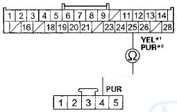
SUNLIGHT SENSOR 5P CONNECTOR
Wire side of female terminals
*1: With navigation
*2: Without navigation
Without automatic lighting
CLIMATE CONTROL UNIT CONNECTOR A (28P)
Wire side of female terminals
SUNLIGHT SENSOR 2P CONNECTOR
Wire side of female terminals
*1: With navigation
*2: Without navigation
Is there continuity? YES-
Go to step 9.
NO-
Repair an open in the wire between the climate control unit and the sunlight sensor.
9. Check for continuity between climate control unit connector B (12P) terminal No. 10 and sunlight sensor 5P connector terminal No. 2 (with automatic lighting), or sunlight sensor 2P connector terminal No. 2 (without automatic lighting).
With automatic lighting
CLIMATE CONTROL UNIT CONNECTOR B (12P)
Wire side of female terminals
SUNLIGHT SENSOR 5P CONNECTOR
Wire side of female terminals
*1: With navigation
*2: Without navigation
Without automatic lighting
CLIMATE CONTROL UNIT CONNECTOR B (12P)
Wire side of female terminals
SUNLIGHT SENSOR 2P CONNECTOR
Wire side of female terminals
*1: With navigation
*2: Without navigation
Is there continuity? YES
-Go to step 10.
NO
-Repair an open in the wire between the climate control unit and the sunlight sensor
10. Reconnect t h e s u n l i g h t sensor 5P connector (with automatic lighting) o r 2P connector (without automatic l i g h t i n g ).
11. Reconnect climate control unit connectors A (28P) andB(12P).
12. Test the sunlight sensor (see page 21 -186).
Is the sunlight sensor OK? YES
-Check for loose wires or poor connections at climate control unit connector and at the sunlight sensor 5P connector (with automatic lighting), or the sunlight sensor 2P connector (without automatic lighting). If the connections are good, substitute a known-good climate control unit, and recheck. If the symptom/indication goes away, replace the original climate control unit (with navigation) (see page 21-190), (without navigation) (see page 21-191) .
NO
-Replace the sunlight sensor (see page 21-186).
DTC B1230 or DTC indicator F and AUTO:
A Short in the Sunlight Sensor Circuit
1. Clear the DTC with the HDS.
2. Turn the ignition switch to LOCK (0), and then to ON (II).
3. Do the self-diagnostic function with the HDS (see page 21-102) or with the climate control unit (see page 21-103).
4. Check for DTCs.
Is DTC B1230 or F and AUTO indicated? YES
-Go to step 5.
NO
-lntermittent failure. Check for loose wires or poor connections on the sunlight sensor circuit.
5. Turn the ignition switch to LOCK (0).
6. Disconnect the sunlight sensor 5P connector (with automatic lighting) or 2P connector (without automatic lighting).
7. Disconnect climate control unit connectors A (28P) andB(12P).
8. Check for continuity between climate control unit connector A (28P) terminal No. 25 and body ground.
CLIMATE CONTROL UNIT CONNECTOR A (28P)
Wire side of female terminals
*1: With navigation
*2: Without navigation
Is there continuity? YES
-Repair a short to body ground in the wire between the climate control unit and the sunlight sensor.B NO
-Go to step 9.
9. Check for continuity between climate control unit connector A (28P) terminal No. 25 and climate control unit connector B (12P) terminal No. 10.
CLIMATE CONTROL UNIT CONNECTOR A (28P)
Wire side of female terminals
CLIMATE CONTROL UNIT CONNECTOR B (12P)
Wire side of female terminals
*1: With navigation
*2: Without navigation
Is there continuity? YES
-Repair a short in the wires between the climate control unit and the sunlight sensor.
NO
-Go to step 10.
10. Reconnect the sunlight sensor 5P connector (with automatic lighting) or 2P connector (without automatic lighting).
11. Reconnect climate control unit connectors A (28P)and B(12P).
12. Test the sunlight sensor (see page 21 -186).
Is the sunlight sensor OK? YES
-Substitute a known-good climate control unit and recheck. If the symptom/indication goes away, replace the original climate control unit (with navigation) (see page 21-190), (without navigation) (see page 21-191).
NO
-Replace the sunlight sensor (see page 21-186).
DTC B1231 or DTC indicator G and AUTO:
An Open in the Evaporator Temperature Sensor Circuit
1. Clear the DTC with the HDS.
2. Turn the ignition switch to LOCK (0), and then to ON (II).
3. Do the self-diagnostic function with the HDS (see page 21-102) or with the climate control unit (see page 21-10.3).
4. Check for DTCs.
Is DTC B1231 or G and AUTO indicated? YES
-Go to step 5. NO-
lntermittent failure. Check for loose wires or poor connections on the evaporator temperature sensor c i r c u i t .
5. Turn the ignition switch to LOCK (0).
6. Disconnect climate control unit connectors A (28P) andB(12P).
7. Check for continuity between climate control unit connector A (28P) terminal No. 23 and evaporator temperature sensor 2P connector terminal No. 2.
CLIMATE CONTROL UNIT CONNECTOR A (28P)
Wire side of female terminals
EVAPORATOR TEMPERATURE SENSOR 2P CONNECTOR
Wire side of female terminals
Is there continuity? YES
-Go to step 8.
NO
-Repair an open in the wire between the climate control unit and the evaporator temperature sensor.
8. Check for continuity between climate control unit connector B (12P) terminal No. 10 and evaporator temperature sensor 2P connector terminal No. 1.
CLIMATE CONTROL UNIT CONNECTOR B (12P)
Wire side of female terminals
EVAPORATOR TEMPERATURE SENSOR 2P CONNECTOR
Wire side of female terminals
*1: With navigation
*2: Without navigation
Is there continuity? YES
-Go to step 9.
NO
-Repair an open in the wire between the climate control unit and the evaporator temperature sensor.
9. Remove the evaporator temperature sensor (see page 21 -67), and test it (see page 21 -58).
Is the evaporator temperature sensor OK? YES
-Check for loose wires or poor connections at climate control unit connectors A (28P), B (12P), and at the evaporator temperature sensor 2P connector. If the connections are good, substitute a known-good climate control unit, and recheck. If the symptom/indication goes away, replace the original climate control unit (with navigation) (see page 21-190), (without navigation) (see page 21-191).
NO
-Replace the evaporator temperature sensor.
DTC B1232 or DTC indicator H and AUTO:
A Short in the Evaporator Temperature Sensor Circuit
1. Clear the DTC with the HDS.
2. Turn the ignition switch to LOCK (0), and then to ON (II).
3. Do the self-diagnostic function with the HDS (see page 21-102) or with the climate control unit (see page 21-103).
4. Check for DTCs.
Is DTC B1232 or H and AUTO indicated? YES-
Go to step 5.
NO
-lntermittent failure. Check for loose wires or poor connections on the evaporator temperature sensor circuit.
5. Turn the ignition switch to LOCK (0).
6. Disconnect climate control unit connectors A (28P) andB(12P).
7. Check for continuity between climate control unit connector A (28P) terminal No. 23 and body ground.
CLIMATE CONTROL UNIT CONNECTOR A (28P)
Wire side of female terminals
Is there continuity? YES
-Repair a short to body ground in the wire between the climate control unit and the evaporator temperature sensor.
NO
-Go to step 8.
8. Check for continuity between climate control unit connector A (28P) terminal No. 23 and climate control unit connector B (12P) terminal No. 10.
CLIMATE CONTROL UNIT CONNECTOR A (28P)
Wire side of female terminals
CLIMATE CONTROL UNIT CONNECTOR B (12P)
Wire side of female terminals
*1: With navigation
*2: Without navigation
Is there continuity? YES
-Repair a short in the wires between the climate control unit and the evaporator temperature sensor.
NO
-Go to step 9.
9. Remove the evaporator temperature sensor (see page 21-67), and test it (see page 21-58).
Is the evaporator temperature sensor OK? YES-
Substitute a known-good climate control unit, and recheck. If the symptom/indication goes away, replace the original climate control unit (with navigation) (see page 21-190), (without navigation) (see page 21-191).
NO
-Replace the evaporator temperature sensor.
DTC B1233 or DTC indicator A and A/C ON:
An Open in the Driver's Air Mix Control Motor Circuit
1. Clear the DTC with the HDS.
2. Turn the ignition switch to LOCK (0), and then to ON (II).
3. Do the self-diagnostic function with the HDS (see page 21 -102) or with the climate control unit (see page 21-103).
4. Check for DTCs.
Is DTC B1233 or A and A/C ON indicated? YES
-Go to step 5.
NO
- CHeeK f u i loose wires or poor connections on the driver's air mix control motor circuit.
5. Turn the ignition switch to LOCK (0).
6. Test the driver's air mix control motor (see page 21-59).
Is the driver's air mix control motor OK? YES-
Go to step 7.
NO-
Replace the driver's air mix control motor (see page 21-60).
7. Disconnect the driver's air mix control motor 7P connector.
8. Disconnect climate control unit connector A (28P) and B(12P).
9, Check for continuity between the following terminals of climate control unit connectors A (28P), B (12P), and the driver's air mix control motor 7P connector.
28P: 7P:
No. 14 No. 3
12P: 7P:
No. 10 No. 7
No. 12 No. 5
CLIMATE CONTROL UNIT CONNECTOR A (28P)
Wire side of female terminals
DRIVER'S AIR MIX CONTROL MOTOR 7P CONNECTOR
Wire side of female terminals
CLIMATE CONTROL UNIT CONNECTOR B (12P)
Wire side of female terminals
DRIVERS AIR MIX CONTROL MOTOR IP CONNECTOR
Wire side of female terminals
* 1: With navigation
*2: Without navigation
Is there continuity? YES
-Check for loose wires or poor connections at climate control unit connectors A (28P), B (12P), and at the driver's air mix control motor 7P connector. If the connections are good, substitute a known-good climate control unit and recheck. If the symptom/indication goes away, replace the original climate control unit (with navigation) (see page 21-190), (without navigation) (see page 21-191).
NO
-Repair an open in the wire(s) between the climate control unit and the driver's air mix control motor.
DTC B1234 or DTC indicator B and A /C ON:
A Short in the Driver's Air Mix Control Motor Circuit
1. Clear the DTC with the HDS.
2. Turn the ignition switch to LOCK (OL and then to ON (II).
3. Do the self-diagnostic function with the HDS (see page 21-102) or with the climate control unit (see page 21-103).
4. Check for DTCs.
Is DTC B1234 or B and A/C ON indicated? YES-
Go to step 5.
NO
—Intermittent failure.Chek for loose wiroc or poor connections on the driver's air mix control motor circuit.
5. Check for DTCs.
Are these DTCs also present; B121B or H and A/C ON, and/or B1220 or L and A/C ON, and/or B1237 or E and A/C ON? YES
-Go to step 13.
NO
-Go to step 6.
6. Turn the ignition switch to LOCK (0).
7. Test the driver's air mix control motor (see page 21-59).
Is the driver's air mix control motor OK? YES
-Go to step 8.
NO
-Replace the driver's air mix control motor (see page21-60) .
8. Disconnect the driver's air mix control motor IP connector.
9. Disconnect climate control unit connectors A (28P) and B (12P).
10. Check for continuity between body ground and climate control unit connector A (28P) terminal No. 14.
CLIMATE CONTROL UNIT CONNECTOR A (28P)
Wire side of female terminals
Is there continuity? YES
-Repair a short to body ground in the wire between the climate control unit and the driver's air mix control motor.
NO
-Go to step 11.
11. Check for continuity between climate control unit connector A (28P) terminal No. 14 and climate control unit connector B (12P) terminal No. 12.
CLIMATE CONTROL UNIT CONNECTOR A (28P)
Wire side of female terminals
CLIMATE CONTROL UNIT CONNECTOR B (12P)
Wire side of female terminals
Is there continuity? YES
-Repair a short in the wires.
NO
-Go to step 12.
12. Turn the ignition switch to ON (II), and measure the voltage between climate control unit connector A (28P) terminal No. 14 and body ground.
CLIMATE CONTROL UNIT CONNECTOR A (28P)
Wire side of female terminals
Is there any voltage? YES
-Repair a short to power in the wire between the climate control unit and the driver's air mix control motor. This short may also damage the climate control unit. Repair a short to power before replacing the climate control unit.
NO
-Substitute a known-good climate control unit, and recheck. If the symptom/indication goes away, replace the original climate control unit (with navigation) (see page 21-190), (without navigation) (see page 21-191 ) . 13. Turn the ignition switch to LOCK (0), and disconnect the climate control unit connector B (12P).
14. Disconnect these items:
• Driver's air mix control motor
• Passenger's air mix control motor
• Recirculation control motor
• Mode control motor
15. Check for continuity between climate control unit connector B (12P) terminal No. 12 and body ground.
CLIMATE CONTROL UNIT CONNECTOR B (12P)
Wire side of female terminals
Is there continuity? YES
-Repair a short to body ground in the wire.
NO
-Go to step 16.
16. Turn the ignition switch to ON (II), and check the same terminal for voltage between the terminal and body ground.
CLIMATE CONTROL UNIT CONNECTOR B (12P)
Wire side of female terminals
Is there any voltage? YES
-Repair a short to power in the wire. This short may have also damaged the climate control unit.
Repair a short to power before replacing the climate control unit.
NO
-Go to step 17.
17. Turn the ignition switch to LOCK (0).
18. Reconnect climate control unit connector B (12P).
19. Turn the ignition switch to ON (ll), and measure the voltage between climate control unit connector B (12P) terminal No. 12 and body ground.
CLIMATE CONTROL UNIT CONNECTOR B (12P)
Wire side of female terminals
Is there about 5 V? YES
-Go to step 20.
NO
-Check for a loose wire or poor connection at climate control unit connector B (12P). If the connection is good, substitute a known-good climate control unit and recheck. If the symptom/indication goes away, replace the original climate control unit (with navigation) (see page 21-190), (without navigation) (see page 21-191).
20. While checking the same terminal for voltage to ground, reconnect these items individually and note the voltage reading each time:
• Driver's air mix control motor
• Passenger's air mix control motor
• Recirculation control motor
• Mode control motor
CLIMATE CONTROL UNIT CONNECTOR B (12P)
Wire side of female terminals
Does the voltage remain at about 5 V? YES
-Substitute a known-good climate control unit and recheck. If the symptom/indication goes away, replace the original climate control unit (with navigation) (see page 21-190), (without navigation) (see page 21-191 ) . NO
-Replace the component that caused the voltage drop.
DTC B123S or DTC indicator C and A /C ON:
A Problem in the Driver's Air Mix Control Linkage, Door, or Motor Circuit
1. Clear the DTC with the HDS.
2. Turn the ignition switch to LOCK (0), and then to ON (II).
3. Do the self-diagnostic function with the HDS (see page 21-102) or with the climate control unit (see page 21-103).
4. Check for DTCs.
Is DTC B1235 or C and A/C ON indicated? YES
-Go to step 5.
NO
-lntermittent failure. Check for loose wires or poor connections on the driver's air mix control motor circuit.
5. Turn the ignition switch to LOCK (0).
6. Test the driver's air mix control motor (see page 21-59).
Is the driver's air mix control motor OK? YES
-Go to step 7.
NO
-Replace the driver's air mix control motor (see page 21-60), or repair the driver's air mix control linkage or door.
7. Disconnect the driver's air mix control motor 7P connector.
8. Disconnect climate control unit connector A (28P).
9. Check for continuity between the following terminals of climate control unit connector A (28P) and the driver's air mix control motor 7P connector.
28P: 7P:
No. 4 No. 2
No. 6 No. 1
CLIMATE CONTROL UNIT CONNECTOR A (28P)
Wire side of female terminals
DRIVER'S AIR MIX CONTROL MOTOR 7P CONNECTOR
Wire side of female terminals
Is there continuity? YES
-Go to step 10.
NO
-Repair an open in the wire(s) between the climate control unit and the driver's air mix control motor.
10. C h e c k f o r c o n t i n u i t y b e t w e e n b o d y g r o u n d a nd climate control unit connector A (28P) terminals No. 4 and No. 6 individually.
CLIMATE CONTROL UNIT CONNECTOR A (28P)
Wire side of female terminals
YES
-Repair a short to body ground in the wire(s) between the climate control unit and the driver's air mix control motor.
NO
-Substitute a known-good climate control unit, and recheck. If the symptom/indication goes away, replace the original climate control unit (with navigation) (see page 21-190), (without navigation) (see page 21-191).
DTC B1236 or DTC indicator D and A /C ON:
An Open in the Passenger's Air Mix Control Motor Circuit
1. Clear the DTC with the HDS.
2. Turn the ignition switch to LOCK (0), and then to ON (II).
3. Do the self-diagnostic function with the HDS (see page 21-102) or with the climate control unit (see page 21-103).
4. Check for DTCs.
Is DTC B1236 or D and A/C ON indicated? YES-Go to step 5.
NO-lntermittent f a i l u r e .Chek for loose wires or poor connections on the passenger's air mix control motor circuit.
5. Turn the ignition switch to LOCK (0).
6. Test the passenger's air mix control motor (see page 21-187).
Is the passenger's air mix control motor OK? YES
-Go to step 7.
NO
-Replace the passenger's air mix control motor (see page21-188).H 7. Disconnect the passenger's air mix control motor 7P connector.
8. Disconnect climate control unit connectors A (28P) and B(12P).
9. Check for continuity between the following terminals of climate control unit connectors A (28P), B (12P), and the passenger's air mix control motor 7P connector.
28P: IP:
No. 13 No. 3
12P: 7P:
No. 10 No. 5
No. 12 No. 7
L I M A T E C O N T R O L U N I T C O N N E C T O R A (28P)
Wire side of female terminals
P A S S E N G E R ' S A I R M I X C O N T R O L MOTOR 7 P C O N N E C T OR
Wire side of female terminals
*1: With navigation
*2: Without navigation
C L I M A T E C O N T R O L U N I T C O N N E C T O R B (12P)
Wire side of female terminals
P A S S E N G E R S A I R M I X C O N T R O L M O T OR 7 P C O N N E C T OR
Wire side of female terminals
*1: With navigation
*2: Without navigation
Is there continuity? YES
-Check for loose wires or poor connections at climate control unit connectors A (28P), B (12P), and at the passenger's air mix control motor 7P connector. If the connections are good, substitute a known-good climate control unit and recheck. If the symptom/indication goes away, replace the original climate control unit (with navigation) (see page 21-190), (without navigation) (see page 21-191 ) . NO
-Repair an open in the wire(s) between the climate control unit and the passenger's air mix control motor.
DTC B1237 or DTC Indicator E and A /C OM:
A Short in the Passenger's Air Mix Control- Motor Circuit
1. Clear the DTC with the HDS.
2. Turn the ignition switch to LOCK (0), and then to ON (II).
3. Do the self-diagnostic function with the HDS (see page 21 -102) or with the climate control unit (see page 21-103).
4. Check for DTCs.
Is DTC B1237 or E and A/C ON indicated? YES
-Go. to step 5.
NO
-lntermittent failure. Check for loose wires or poor connections on the passenger's air mix control motor circuit.
5. Check for DTCs.
Are these DTCs also present; B121B or H and A/C ON, and/or B1220 or L and A/C ON, and/or B1234 or B and A/C ON? YES-Go to step 13.
NO-Go to step 6.
6. Turn the ignition switch to LOCK (0).
7. Test the passenger's air mix control motor (see page 21-187).
Is the passenger's air mix control motor OK? YES
-Go to step 8.
NO
-Replace the passenger's air mix control motor (see page21-188).
8. Disconnect the passenger's air mix control motor 7P connector.
9. Disconnect climate control unit connectors A (28P) and B (12P).
10. Check for continuity between body ground and climate control unit connector A (28P) terminal No. 13.
CLIMATE CONTROL UNIT CONNECTOR A (28P)
Wire side of female terminals
*1: With navigation
* 2 : Without navigation
Is there continuity? YES
-Repair a short to body ground in the wire between the climate control unit and the passenger's air mix control motor.
NO
-Go to step 11.
11. Check for continuity between climate control unit connector A (28P) terminal No. 13 and climate control unit connector B (12P) terminal No. 12.
CLIMATE CONTROL UNIT CONNECTOR A (28P)
Wire side of female terminals
CLIMATE CONTROL UNIT CONNECTOR B (12P)
Wire side of female terminals
*1: With navigation
*2: Without navigation
Is there continuity? YES-
Repair a short in the wires.
NO
-Goto step 12.
12. Turn the ignition switch to ON (II), and measure the voltage between climate control unit connector A (28P) terminal No. 13 and body ground.
CLIMATE CONTROL UNIT CONNECTOR A (28P)
Wire side of female terminals
*1: With navigation
*2: Without navigation
Is there any voltage? YES
-Repair a short to power in the wire(s) between the climate control unit and the passenger's air mix control motor. This short may also damage the climate control unit. Repair a short to power before replacing the climate control unit.
NO
-Substitute a known-good climate control unit, and recheck. If the symptom/indication goes away, replace the original climate control unit (with navigation) (see page 21-190), (without navigation) (see page 21-191).
13. Turn the ignition switch to LOCK (0), and disconnect the climate control unit connector B (12P).
14. Disconnect these items:
• Driver's air mix control motor
• Passenger's air mix control motor
• Recirculation control motor
• Mode control motor
15. Check for continuity between climate control unit connector B (12P) terminal No. 12 and body ground.
CLIMATE CONTROL UNIT CONNECTOR B (12P)
Wire side of female terminals
Is there continuity? YES
-Repair a short to body ground in the w i r e .H NO
-Go to step 16.
16. Turn the ignition switch to ON (II), and check the same terminal for voltage between the terminal and body ground.
CLIMATE CONTROL UNIT CONNECTOR B (12P)
Wire side of female terminals
Is there any voltage? YES
-Repair a short to power in the wire. This short may have also damaged the climate control unit.
Repair a short to power before replacing the climate control unit.
NO
-Go to step 17.
17. Turn the ignition switch to LOCK (0).
18. Reconnect climate control unit connector B (12P).
19. Turn the ignition switch to ON (II), and measure the voltage between climate control unit connector B (12P) terminal No. 12 and body ground.
CLIMATE CONTROL UNIT CONNECTOR B (12P)
Wire side of female terminals
Is there about 5V? YES
-Go to step 20.
NO
-Check for a loose wire or poor connection at climate control unit connector B (12P). If the connection is good, substitute a known-good climate control unit and recheck. If the symptom/indication goes away, replace the original climate control unit (with navigation) (see page 21-190), (without navigation) (see page 21-191 )
20. While checking the same terminal for voltage to ground, reconnect these items individually and note the voltage reading each time:
• Driver's air mix control motor
• Passenger's air mix control motor
• Recirculation control motor
• Mode control motor
CLIMATE CONTROL UNIT CONNECTOR B (12P)
Wire side of female terminals
Does the voltage remain at about 5 V? YES
-Substitute a known-good climate control unit and recheck. If the symptom/indication goes away, replace the original climate control unit (with navigation) (see page 21-190), (without navigation) (see page 21-191).
NO-
Replace the component that caused the voltage d r o p .
DTC B1238 or DTC indicator F and A /C ON:
A Problem in the Passenger's Air Mix Control Linkage, Door, or Motor Circuit
1. Clear the DTC with the HDS.
2. Turn the ignition switch to LOCK (0), and then to ON (II).
3. Do the self-diagnostic function with the HDS (see page 21-102) or with the climate control unit (see page 21-103).
4. Check for DTCs.
Is DTC B1238 or F and A/C ON indicated? YES
-Go to step 5.
NO
-lntermittent failure. Check for loose wires or poor connections on the passenger's air mix control motor circuit.
5. Turn the ignition switch to LOCK (0).
6. Test the passenger's air mix control motor (see page 21-187).
Is the passenger's air mix control motor OK? YES
-Go to step 7.
NO
-Replace the passenger's air mix control motor (see page 21-188), or repair the passenger's air mix control linkage or door.
7. Disconnect the passenger's air mix control motor IP connector.
8. Disconnect climate control unit connector A (28P).
9. Check for continuity between the following terminals of climate control unit connector A (28P) and the passenger's air mix control motor 7P connector.
28P: 7P:
No. 1 No. 2
No. 2 No. 1
CLIMATE CONTROL UNIT CONNECTOR A (28P)
Wire side of female terminals
PASSENGER'S AIR MIX CONTROL MOTOR 7P CONNECTOR
Wire side of female terminals
*1: With navigation
*2: Without navigation
Is there continuity? YES
-Go to step 10.
NO
-Repair an open in the wire(s) between the climate control unit and the passenger's air mix control motor.
10. Check for continuity between body ground and climate control unit connector A (28P) terminals No. 1 and No. 2 individually.
CLIMATE CONTROL UNIT CONNECTOR A (28P)
Wire side of female terminals
YES
-Repair a short to body ground in the wire(s) between the climate control unit and the passenger's air mix control motor.
 Circuit Diagram
'08-09 Models With Navigation
'10 Model With Navigation
'08-09 Models Without Navigation
'10 Model Without Navigation
...
 Climate Control Power and Ground
Circuit Troubleshooting
Climate Control Power and Ground
Circuit Troubleshooting
1. Check the No. 16 (7.5 A) fuse in the driver's
under-dash fuse/ relay box.
is the fuse OK?
YES-Go to step 2.
NO-Replace the fuse, and recheck. If the fuse blows
again, check for a short in ...
See also:
Cam Chain Installation
Special Tools Required
Camshaft Lock Pin Set 07AAB-RWCA120
NOTE:
- Keep the cam chain away from magnetic fields.
- Before doing this procedure, check that the variable
valve timing control (VTC ...
Random Play
To play the tracks on the current
disc in random order, select TRACK
RANDOM, and press ENTER on the
interface selector. As a reminder,
you will see RANDOM next to
TRACK on the screen. To tur ...
Steering Wheel Installation
SRS components are located in this area. Review the
SRS component locations: 4-door {see page 24-21),
2-door (see page 24-23) and the precautions and
procedures (see page 24-25) before doing repair ...