 Honda Accord: Control Unit Input Test
NOTE: Before testing, troubleshoot the multiplex integrated control unit first, using B-CAN System Diagnosis Test Mode A (see page 22-134).
Driver's MICU
1. Turn the ignition switch to LOCK (0), and remove the driver's dashboard lower cover (see page 20-166).
2. Disconnect driver's under-dash fuse/relay box connectors D, Q, and R.
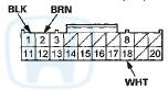
NOTE: All connector views are wire side of female terminals.
CONNECTOR D (16P)
CONNECTOR Q (20P)
CONNECTOR R (24P)
3. Inspect the connector and socket terminals to be sure they are all making good contact.
• If the terminals are bent, loose or corroded, repair them as necessary, and recheck the system.
• If the terminals are OK, go to step 4 .
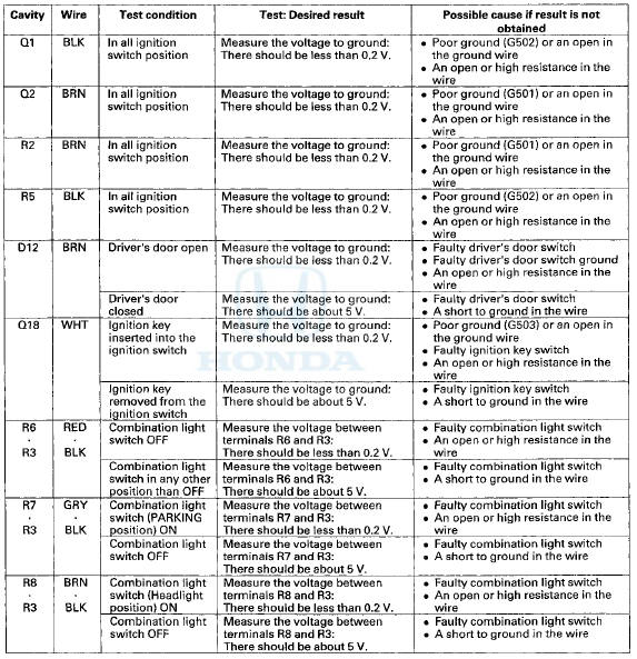
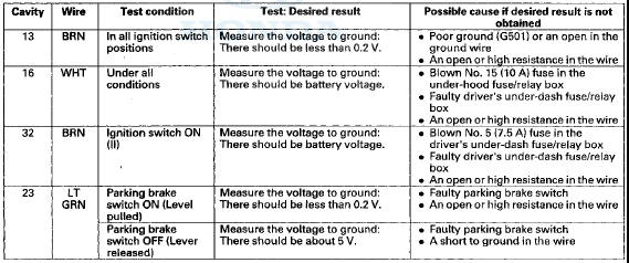
4. Reconnect the connectors, turn the Ignition switch to ON (II), and do these input tests at the following connectors.
• If any test indicates a problem, find and correct the cause, then recheck the system.
• If all the input tests prove OK, go to step 5.
Gauge Control Module
5. Turn the ignition switch to LOCK (0).
6. Remove the gauge control module (see page 22-351), and disconnect the 32P connector from it,
GAUGE CONTROL MODULE 32P CONNECTOR
Wire side of female terminals
7. Inspect the connector and socket terminals to be sure they are all making good contact • If the terminals are bent, loose or corroded, repair them as necessary, and recheck the system.
• If the terminals are OK, go to step 8.
8. Reconnect the connector to the gauge control module, turn the ignition switch to ON (II), and do these input tests at all following connector.
• If any test indicates a problem, find and correct the cause, then recheck the system.
• If the input tests prove OK, go to step 9.
9. Do the Gauge Control Module Self-diagnostic Function (see page 22-332), and check the beeper and the seat belt reminder indicator.
• If the beeper sounds and the seat belt reminder indicator flashes, go to step 10.
• If the beeper does not sound or the seat belt reminder indicator does not flash, replace the gauge control module (see page 22-351).
10. Substitute a known-good gauge control module, and recheck the system.
• If the symptom is gone, the gauge control module is faulty; replace it.
• If the symptom is still present, the driver's MICU is faulty; replace the driver's under-dash fuse/relay box.
- USA models (see page 22-86) - Canada models (see page 22-87)
 Circuit Diagram
...
 Moonroof
...
See also:
Pump Pressure Test w i th T/N 07406-001000A or T/N
07406-001A101
Special Tools Required
-Pump Joint Adapter 07RAK-S040111 o r
P/S Joint
Adapter (pump) 07RAK-S040110
•Hose Joint Adapter 07RAK-S040122
•P/S Pressure Gauge 07408-001000A or
07406-001A1 ...
Injector Replacement
1. Relieve the fuel pressure (see page 11-306).
2. Remove the engine cover,
3. Disconnect the quick-connect fitting (A).
4. Disconnect the Injector connectors (B) and the engine mount control
s ...
System Description
Body Controller Area Network (B-CAN) and Fast Controller Area Network
(F-CAN)
The body controller area network (B-CAN) and the fast controller area network
(F-CAN) share information between
mult ...