 Honda Accord: Charging System Indicator
Circuit Troubleshooting
Honda Accord: Charging System Indicator
Circuit Troubleshooting
troubleshooting the charging system indicator.
1. Turn the ignition switch to ON (II).
Does the charging system indicator come on? YES-
Go to step 2.
NO-
Go to step 14.
2. Start the engine. Hold the engine speed at 2,000 rpm for 1 minute.
Does the charging system indicator go off? YES-
Charging system indicator circuit is OK. Go to the alternator and regulator circuit troubleshooting (see page 4-27 ) . - NO
-Go to step 3.
3. Do the gauge control module self-diagnostic function procedure (see page 22-332).
Does the charging system indicator flash? YES
-Go to step 4.
b-Replace the gauge control module (see page 22-351 ) . - 4. Turn the ignition switch to LOCK (0).
5. Disconnect the alternator 4P connector.
6. Turn the ignition switch to ON (II).
NOTE:
The charging system indicator may come on and then go off.
Does the charging system indicator go off? YES-
Replace the alternator (see page 4-32), or repair the alternator (see page 4-34).H NO
-Go to step 7.
7. Turn the ignition switch to LOCK (0).
8. Connect the Honda Diagnostic System (HDS) to the data link connector (DLC) (see step 2 on page 11-3).
9. Turn the ignition switch to ON (II).
10. Make sure the HDS communicates with the vehicle and the engine control module (ECM)/powertrain control module (PCM). If it does not communicate, troubleshoot the DLC circuit (see page 11-181).
11. Jump the SCS line with the HDS, then turn the ignition switch to LOCK (0).
NOTE: This step must be done to protect the ECM/PCM from damage.
12. Disconnect ECM/PCM connector B (49P).
13. Check for continuity between ECM/PCM connector terminal B46 and body ground.
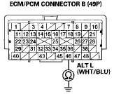
Terminal side of female terminals
Is there continuity? YES-Repair short to ground in the wire between alternator 4P connector terminal No. 3 and ECM/PCM connector terminal B46. il NO-Update the ECM/PCM if it does not have the latest software (see page 11-203), or substitute a known-good ECM/PCM (see page 11-7), then recheck.
If the symptom/indication goes away with a known-good ECM/PCM, replace the original ECM/PCM (see page 11-204).
14. Do the gauge control module self-diagnostic function procedure (see page 22-332).
Does the charging system indicator flash? YES-Gotostep 15.
- NO-Replace the gauge control module (see page 22-351 ) . - 15. Turn the ignition switch to LOCK (0).
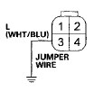
16. Disconnect the alternator 4P connector.
17. Connect alternator 4P connector terminal No. 3 to body ground with a jumper wire.
ALTERNATOR 4P CONNECTOR
Wire side of female terminals
18. Turn the ignition switch to ON (II).
Does the charging system indicator come on? YES-Replace the alternator (see page 4-32), or repair the alternator (see page 4-34).- NO-Disconnect the jumper wire, then go to step 19.
19. Turn the ignition switch to LOCK (0).
20. Connect the HDS to the DLC (see step 2 on page 11-3).
21. Turn the ignition switch to ON (II).
22. Make sure the HDS communicates with the vehicle and the ECM/PCM. If it does not communicate, troubleshoot the DLC circuit (see page 11-181).
23. Jump the SCS line with the HDS, then turn the ignition switch to LOCK (0).
NOTE: This step must be done to protect the ECM/PCM from damage.
24. Disconnect ECM/PCM connector B (49P).
25. Check for continuity between ECM/PCM connector terminal B46 and alternator 4P connector terminal No. 3.
ECM/PCM CONNECTOR B (49P)
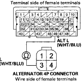
Is there continuity? YES-
Update the ECM/PCM if it does not have the latest software (see page 11-203), or substitute a known-good ECM/PCM (see page 11-7), then recheck.
If the symptom/indication goes away with a known-good ECM/PCM, replace the original ECM/PCM (see page 11-204).B NO-
Repair open in the wire between alternator 4P connector terminal No. 3 and ECM/PCM connector terminal B46
 Circuit Diagram
...
 Alternator and Regulator
Circuit Troubleshooting
Alternator and Regulator
Circuit Troubleshooting
Special Tools Required
Alternator, Regulator, Battery, and Starter Tester
OTC3131*
^Available through the Honda Tool and Equipment
Program 888-424-6857
1. Make sure the battery connections are go ...
See also:
Honda Accord 2013-2026 Owner's Manual
...
Carrier Bearing Replacement
Special Tools Required
Driver Handle, 40 mm I.D. 07746-0030100
1. Check the carrier bearings for wear and rough
rotation. If they rotate smoothly and their rollers show
no signs of wear, the beari ...
Carbon Monoxide Hazard
Your vehicle’s exhaust contains
carbon monoxide gas. Carbon
monoxide should not enter the
vehicle in normal driving if you
maintain your vehicle properly and
follow the information on this ...