 Honda Accord: Balancer Shaft Inspection
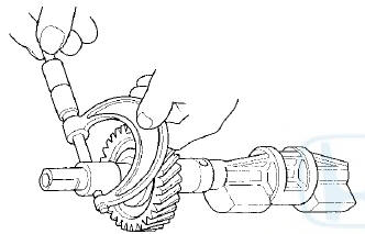
1. Seat the balancer shaft by pushing it away from the oil pump sprocket end of the oil pump.
2. Zero the dial indicator against the end of the balancer shaft, then push the balancer shaft back and forth and read the end play.
Balancer Shaft End Play
Front Balancer Shaft:
Standard (New): 0.063 -0.108 mm
(0.0025- 0.0043 in)
Service Limit: 0.14 mm (0.006 in)
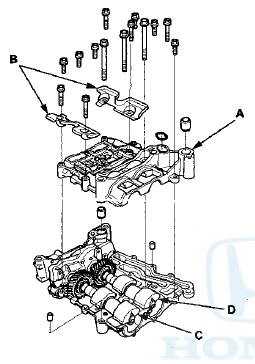
3. Remove the pump housing.
4. Remove the upper balancer shaft holder (with bearings) (A) and the baffle plates (B), then remove the front balancer shaft (C) and the rear balancer shaft (D).
5. Measure the inner diameter of the No. 1 bearing for the front balancer shaft hole and the No. 2 bearing for the rear balancer shaft hole.
Bearing Inner Diameter
Front:
Standard (New): 20.000-”20.020 mm
(0.7874-0.7882 in)
Service Limit: 20.03 mm (0.789 in)
Rear:
Standard (New): 24.000-24.020 mm
(0.9449-0.9457 in)
Service Limit: 24.03 mm (0.946 in)
Front
Rear
6. Measure the diameters of the No. 1 journal on the front balancer shaft and the No. 2 journal on the rear balancer shaft.
Journal Diameter
Front:
Standard (News): 19.938-19.950 min
(0.7850-0.7854 in)
Service Limit: 19.92 mm (0.784 in)
Rear:
Standard (New): 23.938-23.950 mm
(0.9424-0.9429 in)
Service Limit: 23.92 mm (0.942 in)
Front
Rear
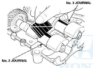
7. Clean the front balancer shaft No. 2 journal, the rear barancer shaft No. 3 journal and the bearing halves with a clean shop towel, then place both balancer shafts into the balancer holder.
8. Place one strip of plastigage across the No. 2 journal and the No. 3 journals.
9. Reinstall the bearings and the upper balancer shaft holder, then tighten the bolts.
NOTE: Do not rotate the balancer shafts during inspection.
10. Remove the upper balancer shaft holder and the bearings again, and measure the widest part with the plastigage. If the front balancer shaft No. 2 and/or the rear balancer shaft No. 3 journals oil clearance is out-of-tolerance, install new bearings, and recheck. If it is still out-of-tolerance, replace the balancer shafts.
Front No. 2 and Rear No. 3 Journals Oil
Clearance
Standard (New): 0.060-0.120 mm
(0.0024-0.0047 in)
Service Limit: 0.15 mm (0.006 in)
11. Align the punch mark on the rear balancer shaft in the center of the two punch marks on the front balancer shaft, then install the balancer shafts on the lower balancer shaft holder.
12. Apply new engine oil to the threads of the 8 mm bolts (A).
13. Install the upper balancer shaft holder (B) with a new O-ring (C).
14. Install the pump housing.
Oil Pump Installation
1. Make sure the No. 1 piston top dead center (TDC) mark (A) lines up with the pointer (B).
NOTE: The other pointer (C) is not used.
2. Align the dowel pin (A) on the rear balancer shaft with the mark (B) on the oil pump.
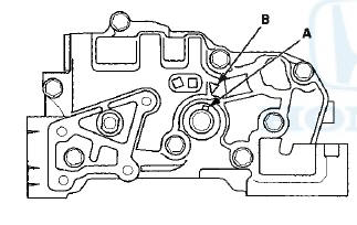
3. To hold the rear balancer shaft, insert a 6 mm long pin punch (A) (Snap-on PPC108LA or equivalent) into the maintenance hole in the balancer shaft holder and through the rear balancer shaft.
4. Turn the plate (A) counterclockwise, to release the lock, then push the oil pump chain auto-tensioner arm (Bland set the first cam (C) to the first edge of the rack (D). Insert a 3.0 mm (0.12 in) diameter pin (E) into the hole (F).
NOTE: If the chain tensioner is not set up as described, the tensioner will become damaged.
5. Install the oil pump chain auto-tensioner (A).
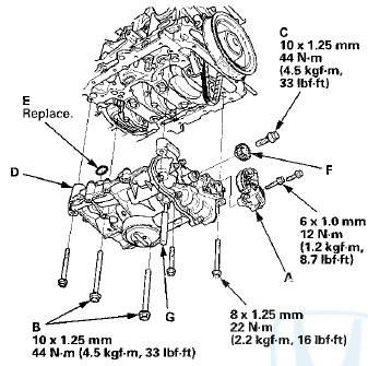
6. Apply new engine oil to the threads of the oil pump mounting bolts (B) and the oil pump sprocket mounting bolt (C), then loosely install the oil pump (D) with a new O-ring (E), then install the oil pump sprocket (F).
7. Tighten the oil pump mounting bolts and the oil pump sprocket mounting bolt.
8. Remove the 6 mm pin punch (G).
9. Remove the 3.0 mm (0.12 in) diameter pin (A) from the oil pump chain auto-tensioner.
10. Install the oil pan (see page 7-30).
 Oil Pump Overhaul
Exploded View
Oil Pump Removal
1. Turn the crankshaft pulley so its top dead center (TDC)
mark (A) lines up with the pointer (B).
NOTE: The other pointer (C) is not used.
2. Remove the oil ...
 Oil Pump Chain inspection
1. Remove the oil pan (see page 7-11).
2. Measure the oil pump chain auto-tensioner rod
length. If the length is over the service limit, replace
the oil pump chain (see page 8-25).
Oil Pump Chai ...
See also:
General Troubleshooting Information
How to Check for DTCs with the HDS
There are three methods used to check for DTCs. The recommended method is to
use the Honda Diagnostic System
(HDS) with the appropriate software, plugged into th ...
For Safe Driving
The following pages explain your vehicle's safety features and how to use
them
properly. The safety precautions below are ones that we consider to be among the
most important. ...
Shift Cable Replacement
1. Remove the center console (see page 20-158).
2. Move the shift lever to R.
3. Remove the nut securing the shift cable end.
5. Rotate the socket holder retainer (A) counterclockwise
(B) ...