 Honda Accord: Transmission Disassembly
Exploded View-Clutch Housing
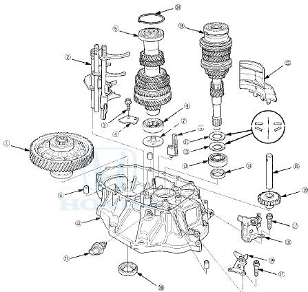
1.DIFFERENTIAL ASSEMBLY
2.SHIFT FORK ASSEMBLY
3.6 mm FLANGE BOLT 13 N-m (1.3 kgf-m, 9.4 Ibf-ft)
4.BEARING SET PLATE
5.COUNTERSHAFT ASSEMBLY
6.NEEDLE BEARING
7.OIL GUIDE PLATE C
8.4 x 2 0 mm DOWEL PIN
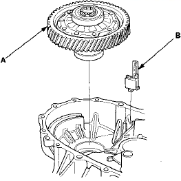
9.MAGNET
10.MAINSHAFT ASSEMBLY
11.28 mm WASHER
12.28 mm SPRING WASHER
13.BALL BEARING
14.28 x 43 x 7 mm OIL SEAL Replace.
15.REVERSE IDLER GEAR SHAFT
16.REVERSE IDLER GEAR
17.6mm SPECIAL BOLT 15 N-m (1.5 kgfm, 11 Ibf-ft)
18.REVERSE SHIFT FORK
19.REVERSE LOCK CAM
20.35 x 58 x 8 mm OIL SEAL Replace.
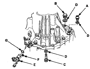
21.BACK-UP LIGHT SWITCH 29 N-m (3.0 kgf-m, 22 Ibf-ft)
22.CLUTCH HOUSING
23.BAFFLE PLATE
24.72 mm SNAP RING
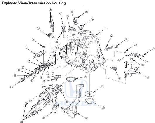
1. TRANSMISSION HOUSING
2. 10 mm SEALING WASHER Replace.
3. 10 mm FLANGE BOLT 44 N-m (4.5 kgf-m, 33 Ibfft)
4. 8 mm FLANGE BOLT 27 Nm (2.8 kgf-m, 20 Ibfft)
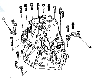
5. TRANSMISSION HANGER A
6. INTERLOCK BOLT 39 N-m (4.0 kgf-m, 29 Ibfft)
7. OIL GUIDE PLATE M
8. 7 2 mm SHIM
9. O I L GUTTER PLATE
10. 80 mm SHIM
11. 8 x 1 4 mm DOWEL PIN
12. CHANGE LEVER ASSEMBLY
13. 6 mm FLANGE BOLT 12 N-m (1.2 kgf-m, 8.7 Ibfft)
14. DETENT BOLT 22 N-m (2.2 kgf-m, 16 Ibfft)
15. 12 mm SEALING WASHER Replace.
16. SPRING
17. STEEL BALL
18. TRANSMISSION HANGER B
19. TRANSMISSION HANGER C
20. 20 mm SEALING WASHER Replace.
21. FILLER PLUG 44 N-m (4.5 kgf-m, 33 Ibfft)
22. 40 x 56 x 8 mm OIL SEAL Replace.
23. 14 mm SEALING WASHER Replace.
24. DRAIN PLUG 39 N m (4.0 kgf-m, 29 Ibfft)
25. 32 mm SEALING CAP 34 Nm (3.5 kgf-m, 25 Ibfft)
26. 10 mm FLANGE BOLT 44 N-m (4.5 kgf-m, 33 Ibfft)
27. 20 mm BOLT 44 Nm (4.5 kgf-m, 33 Ibfft)
28. 20 mm SEALING WASHER Replace.
29. OUTPUT SHAFT (COUNTERSHAFT) SPEED SENSOR
30. O-RING Replace.
31. PLAIN WASHER
32. 6 mm FLANGE BOLT 12 N-m (1.2 kgf-m, 8.7 Ibfft)
NOTE: Place the clutch housing on two pieces of wood thick enough to keep the mainshaft from hitting the workbench.
1. Remove the release bearing and the release fork (see page 12-20).
2. Remove the detent bolts (A), the 12 mm sealing washers (B), the springs (D), the steel balls (E), and the back-up light switch (F).
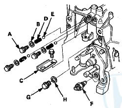
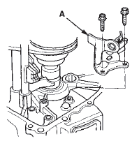
3. Remove transmission hanger C, the 20 mm bolt (G), and the 20 mm sealing washer (H).
4. Remove the interlock bolt (A), the change lever assembly (B), and the 8 x 1 4 mm dowel pins (C).
5. Remove the drain plug (A), the filler plug (B), the 10 mm flange bolt (C), and the sealing washers (D).
6. Remove the output shaft (countershaft) speed sensor (E), the plain washer (F), and the O-ring (G).
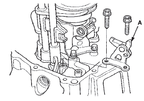
7. Loosen the 8 mm flange bolts in a crisscross pattern in several steps, then remove them with transmission hanger A and transmission hanger B.
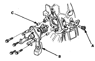
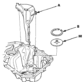
8. Remove the 32 mm sealing cap (A).
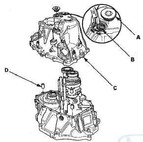
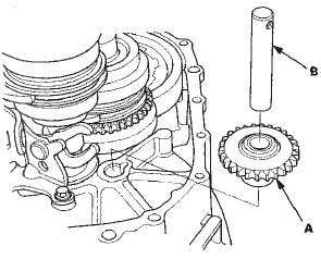
9. While expanding the 72 mm snap ring (B) on the countershaft ball bearing with snap ring pliers, lift the transmission housing (C). Release the snap ring pliers, and remove the transmission housing and the three 14 x 20 mm dowel pins (D).
10. Remove the baffle plate (A).
11. Remove the reverse lock cam (A).
12. Remove the reverse idler gear (A) and the reverse idler gear shaft (B).
13. Remove the reverse shift fork (A).
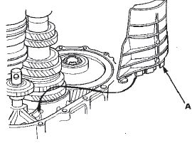
14. Apply tape to the mainshaft splines to protect the seal, then remove the mainshaft assembly (A) and the countershaft assembly (B) with the shift fork assembly (C) from the clutch housing (D).
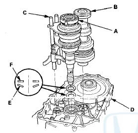
15. Remove the 28 mm spring washer (E) and the 28 mm washer (F).
16. Remove the differential assembly (A) and the magnet (B).
17. Remove the oil gutter plate (A), the 72 mm shim (B), and oil guide plate M.
 Transmission Installation
Special Tools Required
- Engine Support Hanger, A and Reds AAR-T1256*
- Engine Hanger Adapter VSB02C000015*
- Subframe Adapter VSB02C000016*
- Subframe Alignment Pin 070AG-SJAA10S
*: Are availabl ...
 Reverse Shift Fork Clearance Inspection
1. Measure the clearance between the reverse Idler gear
(A) and the reverse shift fork (B) with a feeler gauge
(C). If the clearance exceeds the service limit, go to
step 2.
Standard; 0.20-0.59 mm ...
See also:
Inflation Guidelines
Keeping the tires properly inflated
provides the best combination of
handling, tread life, and riding
comfort.
Underinflated tires wear unevenly,
adversely affect handling and fuel
economy, ...
A Few Words About Safety
Your safety, and the safety of others, is very important. And
operating this vehicle safely is an important responsibility.
To help you make informed decisions about safety, we have
provided op ...
Driver's Seat Position Sensor Operation Check
Check the driver's seat position sensor after driver's seat
position sensor replacement.
1. Make sure the driver's seat is all the way forward
position.
2. Make sure the ignition switch is in L ...