 Honda Accord: Clutch Clearance Inspection
Special Tools Required
Clutch Compressor Attachment 07ZAE-PRP0100
1. Inspect the clutch piston, the clutch discs, the clutch plates, and the clutch end-plate for wear and damage (see page 14-303), and inspect the clutch wave-plate phase difference (see page 14-304), if necessary.
2. Install the clutch piston in the clutch drum. Do not install the O-rings during inspection.
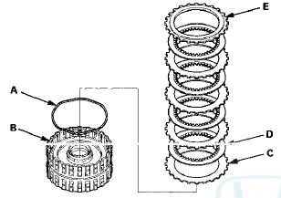
3. Install the waved spring (A) in the 1st clutch drum (B).
Install the clutch flat-plate (C), then starting with the clutch disc, alternately install the clutch discs (D) (5) and the clutch wave-plates (E) (4), then install the clutch end-plate (F) with the flat side toward the top disc.
4. Install the waved spring (A) in the 2nd clutch drum (B).
Install the clutch flat-plate (C), then starting with the clutch disc, alternately install the clutch discs (D) (6) and the wave-plates (E) (5), then install the clutch end-plate (F) with the flat side toward the top disc.
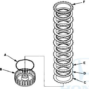
5. Install the waved spring (A) in the 3rd clutch drum (B).
Install the clutch flat-plate (C), then starting with the clutch disc, alternately install the clutch discs (D) (6) and the clutch wave-plates (E) (5), then install the clutch end-plate (F) with the flat side toward the top disc.
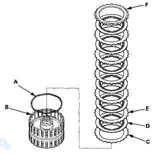
6. Install the waved spring (A) in the 4th clutch drum (B).
Starting with the clutch wave-plate, alternately install the clutch wave-plates (C) (4) and the clutch discs (D) (4), then install the clutch end-plate (E) with the flat side toward the top disc.
7. Install the waved spring (A) in the 5th clutch drum (B).
Starting with the clutch wave-plate, alternately install the clutch wave-plates (C) (4) and the clutch discs (D) (4), then install the clutch end-plate (E) with the flat side toward the top disc.
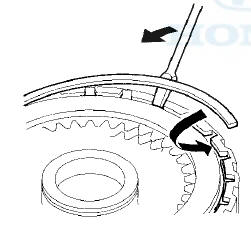
8. Install the snap ring using a screwdriver.
9. Set a dial indicator (A) on the clutch end-plate (B).
10. Zero the dial indicator with the clutch end-plate lifted up to the snap ring (C).
11. Release the clutch end-plate to lower the clutch end-plate, then put the clutch compressor attachment on the clutch end-plate (A).
12. Press the clutch compressor attachment down with 147 N (15 kgf, 33 Ibf) (B) using a force gauge, and read the dial indicator (C).
13. The dial indicator reads the clearance (D) between the clutch end-plate and the top disc (E). Take measurements in at least three places, and use the average as the actual clearance.
Clearance between Clutch End-Plate and Top Disc
Standard:
1st Clutch: 1.38-1.58 mm (0.054-0.062 in)
2nd Clutch: 1.14-1.34 mm (0.045-0.053 in)
3rd Clutch: 1.23-1.43 mm (0.048-0.056 in)
4th Clutch: 0.93-1.13 mm (0.037-0.044 in)
5th Clutch: 0.93-1.13 mm (0.037-0.044 in)
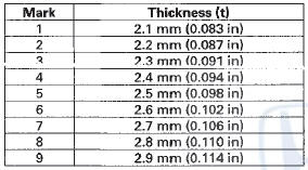
14. If the clearance is out of the standard, select a new clutch end-plate from the following table.
1ST CLUTCH END-PLATES
2ND CLUTCH END-PLATES
3RD, 4TH, and STH CLUTCH END-PLATES
15. Install a new clutch end-platef and recheck the clearance. If the thickest clutch end-plate is installed, but the clearance is still over the service limit, replace the clutch discs and the clutch plates.
 Clutch Wave-plate Phase Difference
Inspection
Clutch Wave-plate Phase Difference
Inspection
1. Place the clutch wave-plate (A) on a surface plate, and
set a dial indicator (B) on the wave-plate.
2. Find the bottom (C) of a phase difference of the
wave-plate, zero the dial indicator an ...
 1st, 2nd, and 3rd Clutch Reassembly
Special Tools Required
Clutch Spring Compressor Set 07LAE-PX40000
NOTE: Hold the spring compressor in a vise with soft
jaws. Be careful not to damage the clutch drum.
1 Soak the clutch discs tho ...
See also:
Maintain a Proper Sitting Position
After all occupants have adjusted
their seats and head restraints, and
put on their seat belts, it is very
important that they continue to sit
upright, well back in their seats, with
their f ...
Fuel Pressure Relieving
Before disconnecting fuel lines or hoses, relieve
pressure from the system by disabling the fuel pump,
running the engine until it stalls, then and disconnecting
the fuel line/quick connect fitting ...