 Honda Accord: Circuit Diagram
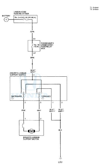
Eighth generation (2008–2012) / Honda Accord MK8 2008-2012 Service Manual / Body Electrical / Power Lumbar Support / Circuit Diagram

 Switch Test/Replacement
1. Separate the lumbar support switch cover (A) from
the switch (B).
2. Disconnect the 5P connector (C) from the switch.
3. Check for continuity between the terminals in each
switch position a ...
See also:
DTC Troubleshooting
DTC P0420: Catalyst System Efficiency Below
Threshold
NOTE:
- Before you troubleshoot, record all freeze data and
any on-board snapshot, and review the general
troubleshooting information (see pa ...
Disc Scan
When you press the SCAN side of
the SCAN/A. SEL bar repeatedly
until you see D-SCAN in the center
display, or push the interface
selector to the right, the first track of
the current disc pl ...