 Honda Accord: Brake Booster Replacement
1. Remove the cowl cover (see page 20-278).
2. Remove the strut brace (if equipped) (see page 20-306).
3. Remove the master cylinder (see page 19-26).
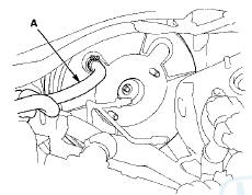
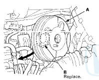
4. Disconnect the brake booster vacuum hose (A) from the brake booster.
5. Remove the under-hood fuse/relay box bracket (A), then remove the engine wire harness clamps (B).
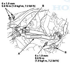
6. Remove the brake lines (A) from the hose clamp (B).
7 Remove the lock pin (A) and the clevis pin (B), then disconnect the yoke from the brake pedal.
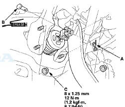
8. Remove the brake booster mounting nuts (C).
9. Remove the brake booster (A) from the engine compartment.

- Be careful not to damage the brake booster mounting surfaces and the threads on the booster studs.
- Be careful not to bend or damage the brake lines.
NOTE: Use the new brake booster gasket (B) during reassembly.
10. Install the brake booster in the r e v e r s e order of removal, and note these items: - Install the master cylinder after installing the brake booster (see page 19-26).
- Check the brake pedal height and free play after installing the master cylinder, and adjust it if necessary (see page 19-6).
- Bleed the brake system (see page 19-9).
 Brake Booster Test
Functional Test
1. With the ignition switch in LOCK (0), press the brake
pedal several times to deplete the vacuum reservoir,
then press the brake pedal hard and hold it for
15 seconds. If the bra ...
 Rear Brake Pad Inspection and Replacement
CAUTION
Frequent inhalation of brake pad dust, regardless of
material composition, could be hazardous to your
health.
- Avoid breathing dust particles.
-Never use an air hose or brush to clea ...
See also:
Authorized Manuals
Purchasing Factory Authorized Manuals (U.S. only)
The publications shown below can be purchased from Helm
Incorporated. You can order by phone or online:
Call Helm Inc. at 1-800-782-4356 (credit c ...
ATF Level Check
NOTE:
-Keep all foreign particles out of the transmission.
-Check the ATF level within 60—90 seconds after
turning the engine off.
-Higher ATF level may be indicated if the radiator fan
...