 Honda Accord: Driver's Under-dash Fuse/Relay Box
(MICU) Removal and Installation
Honda Accord: Driver's Under-dash Fuse/Relay Box
(MICU) Removal and Installation
Special Tools Required
Relay Puller 07AAC-000A1A0
USA models
NOTE; SRS components are located in this area. Review the SRS component locations 4-door (see page 24-21), 2-door (see page 24-23), and precautions and procedures (see page 24-25) before doing repairs or servicing.
Removal
1. Do the battery terminal disconnection procedure (see page 22-91).
2. Remove the driver's dashboard lower cover (see page 20-166), and the driver's kick panel: • 4-door (see page 20-107) • 2-door (see page 20-105) 3. Disconnect the connectors from the fuse side of the driver's under-dash fuse/relay box (A).
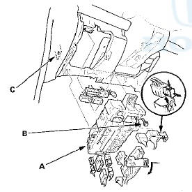
4. Remove the mounting bolt (B), release the tab (C), and pull the driver's under-dash fuse/relay box away from the body.
5. Disconnect the connectors from the back side of the driver's under-dash fuse/relay box, then remove the driver's under-dash fuse/relay box.
6. Carefully remove the relays by prying under the base of the relay using the relay puller (see page 22-93).
NOTE: Do not use pliers. Pliers will damage the relays, which could cause the engine to stall or not start.
Installation
1. Install the relays and connect the connectors to the driver's under-dash fuse/relay box, then install the driver's under-dash fuse/relay box in the reverse order of removal.
2. Install the removed parts in the reverse order of removal.
3. Do the battery terminal reconnection procedure steps 1 to 4 (see page 22-91).
4. Register the immobilizer system with the HDS (see page 22-439).
NOTE: The imoes unit is built into the driver's MICU which is part of the driver's under-dash fuse/relay box. Because of this construction, t h e i m o e c m " o t h e registered, or the vehicle will not start.
5. Confirm that all systems work properly.
Special Tools Required
Relay Puller 07AAC-000A1A0
Canada models
NOTE; SRS components are located In this area. Review the SRS component locations 4-door (see page 24-21), 2-door (see page 24-23), and precautions and procedures (see page 24-25) before doing repairs or servicing.
Removal
1. Do the battery terminal disconnection procedure (see page 22-91).
2. Remove the driver's dashboard lower cover (see page 20-166), and the driver's kick panel: • 4-door (see page 20-107) • 2-door (see page 20-105) 3. Loosen the bolts (A), then remove the bolt (B) from the bracket (C).
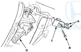
4. Remove the bracket from the driver's under-dash fuse/relay box (D).
5. Disconnect the connectors from the fuse side of the driver's under-dash fuse/relay box (A).
6. Remove the screws and cover (B) from the driver's under-dash fuse/relay box.
7. Remove the mounting bolt (C), release the tab(D), and pull the driver's under-dash fuse/relay box away from the body.
8. Disconnect the connectors from the back side of the driver's under-dash fuse/relay box, then remove the driver's under-dash fuse/relay box.
9. Carefully remove the relays by prying under the base of the relay using the relay puller (see page 22-93).
NOTE: Do not use pliers. Pliers will damage the relays, which could cause the engine to stall or not start.
Installation
1. Install the relays and connect the connectors to the driver's under-dash fuse/relay box, then install the driver's under-dash fuse/relay box in the reverse order of removal.
2. Install the removed parts in the reverse order of removal.
3. Do the battery terminal reconnection procedure steps 1 to 4 (see page 22-91).
4. Register the immobilizer system with the HDS (see page 22-439).
NOTE: The imoes unit is built into the driver's MICU which is part of the driver's under-dash fuse/relay box. Because of this construction, the imoes must be registered, or the vehfole not start.
5. Confirm that all systems work properly.

 Passenger's Under-dash Fuse/Relay
Box (MICU) Removal and
Installation
Passenger's Under-dash Fuse/Relay
Box (MICU) Removal and
Installation
NOTE: SRS components are located in this area. Review
the SRS component locations 4-door (see page 24-21),
2-door (see page 24-23), and precautions, and
procedures (see page 24-25) before doing rep ...
See also:
Selecting a Memorized Position
To select a memorized position, do
this:
1. Make sure the parking brake is set
and the shift lever is in Park
(automatic).
2. Press the desired memory button
(1 or 2) until you hear a beep ...
Sunvisor Removal/Installation
NOTE:
- Put on gloves to protect your hands.
- Take care not to bend or scratch the headliner.
- When prying with a flat-tip screwdriver, wrap it with
protective tape to prevent damage.
1. ...
General Troubleshooting Information
DTC (Diagnostic Trouble Codes)
The self-diagnostic function of the SRS unit allows it to
locate the causes of system problems and store this
information in memory. For easier troubleshooting, this
...