 Honda Accord: Ball Joint Removal
Special Tools Required
- Ball Joint Thread Protector, 14 mm 07AAE-SJAA100
- Ball Joint Thread Protector, 12 mm 07AAF-SDAA100
- Ball Joint Thread Protector, 10 mm 07AAF-SECA120
- Ball Joint Remover, 32 mm 07MAC-SL0A102
- Ball Joint Remover, 28 mm 07MAC-SL0A202

Always use a ball joint remover to disconnect a ball joint.
Do not strike the housing or any other part of the ball joint connection to disconnect it.
1. Install a hex nut (A) or the ball joint thread protector onto the threads of the ball joint (B).
2. Apply grease to the ball joint remover on the areas shown (A). This will ease the installation of the tool, and prevent damage to the pressure bolt (B) threads.
3. Loosen the pressure bolt (A), and install the ball joint remover as shown. Insert the jaws carefully, making sure not to damage the ball joint boot. Adjust the jaw spacing by turning the adjusting bolt (B).
NOTE: Fasten the safety chain (C) securely to a suspension arm or the subframe (D). Do not fasten it to a brake line or wire harness.
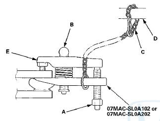
4. After adjusting the adjusting bolt, make sure the head of the adjusting bolt is in the position shown to allow the jaw (E) to pivot.
5. With a wrench, tighten the pressure bolt until the ball joint pin pops loose from the ball joint connecting hole. If necessary, apply penetrating type lubricant to loosen the ball joint pin.
NOTE: Do not use pneumatic or electric tools on the pressure bolt.
6. Remove the ball joint remover, then remove the nut or the ball joint thread protector from the end of the ball joint pin, and pull the ball joint out of the ball joint connecting hole. Inspect the ball joint boot, and replace it if damaged.
 Wheel Bolt Replacement
Special Tools Required
B a i l Joint Remover, 28 mm 07MAC-SL0A202
- Do not use a hammer or impact tools (pneumatic or
electric) to remove and install the wheel bolts.
- Be careful not to damag ...
 Ball Joint Boot Inspection / Replacemen
Special Tools Required
- Clip Guide, 45 mm 070AG-SJA0300
-Clip Guide, 41 mm 07974-SA50700
1. Check the ball joint boot for weakness, damage,
cracks, and grease leaks.
NOTE:
- If the ball joint ...
See also:
Changing the Set Speed
You can increase the set cruising
speed in any of these ways:
Press and hold the RES/ACCEL
button. When you reach the
desired cruising speed, release the
button.
Push on the accelerator peda ...
Lubricants a n d Fluids
For the details of the lubrication points and the type of lubricants to be
applied, refer to the illustrated index and the
various work procedures (such as Assembly/Reassembly, Replacement Overhaul ...
Driver and Passenger Safety
This section gives you important
information about how to protect
yourself and your passengers. It
shows you how to use seat belts. It
explains how your airbags work. And
it tells you how to ...