 Honda Accord: Wheel Alignment
The suspension can be adjusted for front and rear toe.
Pre-Alignment Checks
For proper inspection and adjustment of the wheel ; alignment, do these checks: 1. Release the parking brake-to avoid an Incorrect measurement.
2. Make sure the suspension is not modified.
3. Make sure the fuel tank is full, and that the spare tire, the jack, and the t o o l s are in place on the vehicle.
4. Check the tire size and tire pressure.
Tire size (4-door):
IX, LX-P, LX PZEV, and LX-P PZEV models:
Front/Rear: P215/60R16 94H
EX, EX-L, EX PZEV, and EX-L PZEV models:
Front/Rear:-P225/50B.i7 93V
Tire size (2-door):
Front/Rear: P225/50R17 93V
Tire pressure (4-door) (at cold):
LX, LX-P, LX PZEV, and LX-P PZEV models:
Front/Rear: 210 kPa (2.1 kgf/cm2,30 psi)
EX, EX-L, EX PZEV, and EX-L PZEV models:
Front/Rear: 22В§ kPa (2.2 kgf/cm2,32 psi)
Tire pressure (2-door) (at cold):
Front/Rear: 220 kPa (2.2 kgf/cm2,32 psi)
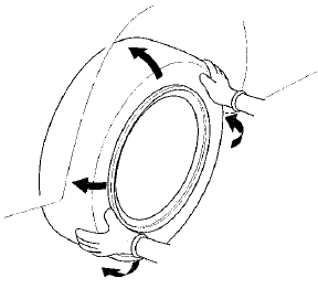
5. Check the runout of the wheels and tires (see page 18-8).
6. Check the suspension ball joints (Raise and support the vehicle (see page 1-13). Hold a tire with your hands, a n d m o v e it up and down and right and left to check f o r movement).
7. Before doing alignment inspections, be sure to remove all extra weight from the vehicle, and no one should be inside the vehicle (driver or passengers).
8. Lower the vehicle to ground. Bounce the vehicle up and down several times to stabilize the suspension.
9. Check that the steering column is set at the center tilt and telescopic position.
Caster Inspection
Use commercially available computerized four wheel alignment equipment to measure wheel alignment (caster, camber, toe, and turning angle). Follow the equipment manufacturer's instructions.
1. Check the caster angle.
Caster angle:
4-door: 3 В° 48 ' + 0 В° 2 5 -, 0 05-
2-door: 3 В° 47 , + 0 В° 2 5 , o05
(Maximum difference between the right and left side: 0 В° 45 *)
- If the measurement is within specifications, measure the camber angle.
- If the measurement is not within specifications, check for bent or damaged suspension components.
Camber Inspection
Use commercially available computerized four wheel alignment equipment to measure wheel alignment (caster, camber, toe, and turning angle). Follow the equipment manufacturer's instructions.
1. Check the camber angle.
Camber angle:
Front: 0 В° 00 , + 3 В° - 4 5
Rear: - 1 В° 0 0 , + m
(Maximum difference between the right and left side: 0 В° 30 ')
- If the measurement is within specifications, measure the toe-in.
- If the measurement is not within specifications, check for bent or damaged suspension components.
Front Toe Inspection/Adjustment
Use commercially available computerized four wheel alignment equipment to measure wheel alignment (caster, camber, toe, and turning angle). Follow the equipment manufacturer's instructions.
1. Set the steering column to the middle tilt and telescopic positions. Center the steering wheel spokes, and install a steering wheel holder tool.
2. Check the toe with the wheels pointed straight
Front toe-in: 0 В± 2 mm (0В±0.08 in)
- If adjustment is required, go to step 3.
- If no adjustment is required, go to rear toe inspection/adjustment.
3. Loosen the tie-rod locknuts (A) while holding the flat surface sections (B) of the tie-rod end with a wrench, and turn both tie-rods (C) until the front toe is within specifications.
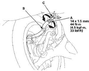
4. After adjusting, tighten the tie-rod locknuts to the specified torque. Reposition the rack-end boot if it is twisted or displaced.
5. Go to rear toe inspection/adjustment.
Rear Toe Inspection/Adjustment
Use commercially available computerized four wheel alignment equipment t o measure wheel alignment (caster, camber, toe, and turning angle). Follow the equipment manufacturer's instructions.
1. Release the parking brake to avoid an incorrect measurement.
2. Check the toe.
Rear toe-in: 2 В± 2 mm (0.08 + 0.08 in)
- If adjustment is required, go to step 3.
- If no adjustment is required, go to turning angle inspection.
3. Hold the adjusting bolt (A) on the rear control arm (B), and loosen the self-locking nut (C).
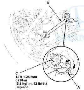
4. Replace the self-locking nut with a new one, and lightly tighten it.
NOTE: Always use a new self-locking nut whenever it has been tightened to the specified torque.
5. Adjust the rear toe by turning the adjusting bolt until the toe is correct.
6. Tighten the self-locking nut while holding the adjusting bolt to the specified torque.
Turning Angle Inspection
Use commercially available computerized four wheel alignment equipment to measure wheel alignment (caster, camber, toe, and turning angle). Follow the equipment manufacturer's instructions.
1. Turn the wheel right and left while applying the brake, and measure the turning angle of both wheels.
Turning angle:
Inward: 39В° 00' В± 2 В°
Outward (reference): 31 В° 5 0 '
2. If the measurement is not within the specifications, even up both sides of the tie-rod threaded section length while adjusting the front toe. If it is correct, but the turning angle is not within the specifications, check for bent or damaged suspension components.
 Component Location Index
Frot Suspension
Rear Suspension
...
 Wheel Bearing End Play Inspection
1. Raise and support the vehicle (see page 1-13).
2. Remove the wheels.
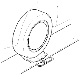
3 . Install suitable flat washers (A) and the wheel nuts.
Tighten the nuts to the specified torque to hold the
brake d ...
See also:
Immobilizer Key Registration
NOTE:
• The HDS is required for registration of the immobilizer
keys.
• Programming the immobilizer also programs the
keyless transmitter.
• Check for aftermarket electrical eq ...
Transmission Disassembly
Exploded View-Clutch Housing
1.DIFFERENTIAL ASSEMBLY
2.SHIFT FORK ASSEMBLY
3.6 mm FLANGE BOLT
13 N-m (1.3 kgf-m, 9.4 Ibf-ft)
4.BEARING SET PLATE
5.COUNTERSHAFT ASSEMBLY
6.NEEDLE BEARING
7.OI ...
Paint Code
...