 Honda Accord: VTC Actuator, Exhaust Camshaft
Sprocket Replacement
Honda Accord: VTC Actuator, Exhaust Camshaft
Sprocket Replacement
Removal
1. Remove the cam chain (see page 6-62).
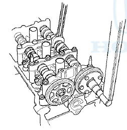
2. Hold the camshaft with an open-end wrench, then loosen the variable valve timing control (VTC) actuator mounting bolt and the exhaust camshaft sprocket mounting bolt.
3. If the VTC actuator will be reused, do these steps.
-1. Remove the intake camshaft, and seal the retard holes in the No. 1 camshaft journal with tape and a wire tie (see step 6 on page 6-57).
-2. Seal one of the advance holes with tape (see step 7 on page 6-57).
-3. Apply air to the unsealed advance hole to release the lock (see step 8 on page 6-58).
-4. Remove the tape and adhesive residue from the No. 1 camshaft journal.
4. Remove the VTC actuator and the exhaust camshaft sprocket.
Installation
1. Install the VTC actuator and the exhaust camshaft sprocket.
NOTE: Install the VTC actuator while in the unlocked position.
2. Apply new engine oil to the threads of the VTC actuator mounting bolt and the exhaust camshaft mounting bolt, then install them.
3. Hold the camshaft with an open-end wrench, then tighten the bolts.
Specified Torque
VTC Actuator Mounting Bolt:
12 x 1.25 mm
113 N-m (11.5 kgfm, 83 Ibf-ft)
Exhaust Camshaft Sprocket Mounting Bolt:
10x1.25 mm
72 N-m (7.3 kgfm, 53 Ibf-ft)
4. Hold the camshaft, and turn the VTC actuator clockwise until you hear it click. Make sure to lock the VTC actuator by turning it.
5. Install the cam chain (see page 6-64).
 CMP Pulse Plate B Replacement
1. Remove the cylinder head cover (see page 6-73).
2. Remove camshaft position (CMP) sensor B (see page
11-198).
3. Hold the camshaft with an open-end wrench, then
loosen the bolt.
4. Remov ...
 Cylinder Head Inspection for
Warpage
Cylinder Head Inspection for
Warpage
1. Remove the cylinder head (see page 6-76).
2. Inspect the camshaft (see page 6-84).
3. Check the cylinder head for warpage. Measure along
the edges, and three ways across the center.
- If ...
See also:
DTC Troubleshooting
DTC P0461: Fuel Level Sensor (Fuel Gauge
Sending Unit) Circuit Range/Performance
Problem
NOTE:
- Before you troubleshoot record all freeze data and
any on-board snapshot, and review the general
...
Countershaft Disassembly, Inspection,
and Reassembly
1. Inspect the needle bearings for galling and rough movement.
2. Inspect the splines for excessive wear and damage.
3. Check the shaft bearing surface for scoring and excessive wear.
4. Lubr ...