 Honda Accord: Valve Body Repair
NOTE: This repair is only necessary if one or more of the valves in a valve body do not slide smoothly in their bores. Use this procedure to free the valves.
1. Soak a sheet of #600 abrasive paper in ATF for about 30 minutes.
2. Carefully tap the valve body so the sticking valve drops out of its bore. It m a y be necessary to use a small screwdriver to pry the valve free. Be careful not to scratch the bore.
3. Inspect the valve for any scuff marks. Use the ATF-soaked #600 abrasive paper to polish off any burrs that are on the valve, then wash the valve in solvent and dry it with compressed air.
4. Roll up half a sheet of ATF-soaked #600 abrasive paper and insert it in the valve bore of the sticking valve.
Twist the paper slightly, so that it unrolls and fits the bore tightly, then polish the bore by twisting the paper as you push it in and out.
NOTE: The valve body is aluminum and does not require much polishing to remove any burrs.
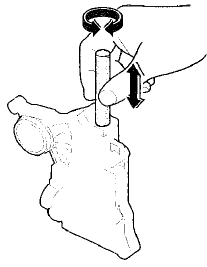
5. Remove the #600 abrasive paper. Thoroughly wash the entire valve body in solvent, then dry it with compressed air.
6. Coat the valve with ATF, then drop it into its bore. It should drop to the bottom of the bore under its own weight. If not, repeat step 4, then retest. If the valve still sticks, replace the valve body.
7. Remove the valve, and thoroughly clean it and the valve body with solvent. Dry all parts with compressed air, then reassemble using ATF as a lubricant.
 Valve Body and ATF Strainer Removal
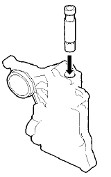
1. Remove the ATF feed pipes (A) and the ATF joint pipes (B).
2. Remove the ATF strainer (C) (two bolts).
3. Remove the regulator valve body (D) (eight bolts).
4. Remove the stator shaft (E) and ...
 Valve Body Valve Installation
1. Coat all parts with ATF before assembly.
2. Install the valves and the springs in the sequence
shown for the main valve body (see page 14-277), the
regulator valve body (see page 14-279), and ...
See also:
Front Brake Disc Replacement
NOTE: Keep any grease off the brake disc and the brake
pads.
1. Raise and support the vehicle (see page 1 -13).
2. Remove the front wheel.
3. Remove the brake hose mounting bolt (A).
4. R ...
Closing Force and Opening Drag
Check
1. Remove the headliner (see page 20-140).
2. Closing force check:
- Cover the leading edge of the glass (A) with a shop
towel (B), and attach a spring scale (C) as shown.
- Have an assistant ...
Circuit Diagram
M/T model
A/T modeS
...