 Honda Accord: Valve Body
Valve Body and ATF Strainer Installation
Exploded View
Torque Specifications:
6 x 1.0 mm: 12 N-m (1.2 kgf m, 8.7 Ibfft)
8 x 1.25 mm: 18 N-m (1.8 kgfm, 13 Ibfft)
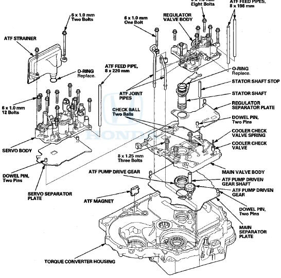
NOTE: Refer to the Exploded View as needed during the following procedures.
1. Make sure that the ATF magnet is clean and installed in the torque converter housing.
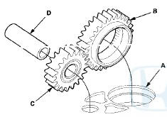
2. Install the main separator plate (A) and the two dowel pins on the torque converter housing. Then install the ATF pump drive gear (B), the ATF pump driven gear (C), and the ATF pump driven gear shaft (D). Install the ATF pump driven gear with its grooved and chamfered side facing down.
3. Install the main valve body (three bolts).
4. Make sure the ATF pump drive gear (A) rotates smoothly in the normal operating direction, and the ATF pump driven gear shaft (B) moves smoothly in the axial and normal operating direction.
5. If the ATF pump drive gear and the ATF pump driven gear shaft do not move smoothly, loosen the main valve body bolts. Realign the ATF pump driven gear shaft, and retighten the bolts to the specified torque, then recheck. Failure to align the ATF pump driven gear shaft correctly will result in a seized ATF pump drive gear or ATF pump driven gear shaft.
6. Make sure that the two check balls and the cooler check valve are in the main valve body, then install the cooler check valve spring in the cooler check valve.
7. Install the servo separator plate and the two dowel pins on the main valve body.
8. Install the servo body (12 bolts).
S. ii isiaii a new O-ring on the ATF strainer, and install the ATF strainer (two bolts) on the servo body.
10. Install the regulator separator plate and the two dowel pins on the main valve body.
11. Install a new O-ring on the stator shaft, and install the stator shaft and the stator shaft stop.
12. Install the regulator valve body (eight bolts).
13. Install the ATF joint pipes (one bolt).
14. Install the ATF feed pipes in the regulator valve body and the servo body.
 4th and 5th Clutch Reassembly
Special Tools Required
Clutch Spring Compressor Set 07LAE PX40000
1. Soak the clutch discs thoroughly in ATF for at least
30 minutes.
2. Install new O-rings (A) on the clutch piston (B). Do not
...
 Transmission Housing
Shaft Assembly and Housing
Installation
Exploded View
NOTE: Refer to the Exploded View as needed during the
following procedure.
1. Install the differential assembly in the torque
converter ...
See also:
Compatible iPod®, iPhone®, and USB Flash Drives
• iPod® and iPhone® Model Compatibility
This system may not work with all software versions
of these devices.
• USB Flash Drives
• Use a recommended USB flash drive of 256 MB or higher. ...
Transmission Number
Transmission Type
88E5: 5-speed Manual
B90A: 5-speed Automatic
Serial Number
1000001-: B90A
8000001-: 88E5 ...
Carrier Bearing Replacement
Special Tools Required
Driver Handle, 40 mm I.D. 07746-0030100
1. Check the carrier bearings for wear and rough
rotation. If they rotate smoothly and their rollers show
no signs of wear, the beari ...