 Honda Accord: Transmission Removal
Special Tools Required
- Engine Support Hanger, A and Reds AAR-T1256*
- Engine Hanger Adapter VSB02C000015*
- Subframe Adapter VSB02C000016*
*: Are available through the Honda Tool and Equipment Program 888-424-6857.
NOTE: Use fender covers to avoid damaging painted surfaces.
1 Secure the hood in the wide open position with the support strut.
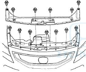
2. Remove the front grille cover.
3. Do the battery removal procedure (see page 22-92).
4. Remove the air cleaner assembly (see page 11-332).
5. Remove the battery base bolts (A), loosen the two bolts (B)f remove the cable clamp (C) and the harness bracket bolt (D), then remove the battery base (E).
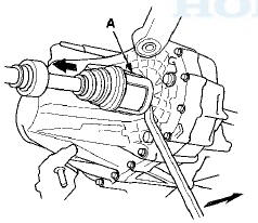
6. Remove the slave cylinder mounting bolts (A) and the bracket mounting nut (B), then carefully move the slave cylinder out of the way to avoid bending the clutch line.
NOTE: Do not press the clutch pedal after the slave cylinder has been removed.
7. Remove the nut (A) and the clamp (B), then move the under-hood fuse/relay box (C) out of the way.
8. Remove the lock pins (A), the shift cable bracket bolts (B), and the shift cable bracket (C), then disconnect the shift cables (D) from the change lever assembly (E).
Carefully remove both cables and the bracket together to avoid bending the cables.
9. Disconnect the output shaft (countershaft) speed sensor connector (A), the back-up light switch connector (B), and the harness clamp (C).
10. Remove the bolts (A), the harness clamp (B), and the bracket (C).
11. Remove the hose from the clamp (A) and the nuts (B),
then remove the strut brace (C).
12. Remove the evaporative emission (EVAP) canister hose (A) and the brake booster vacuum hose (B).
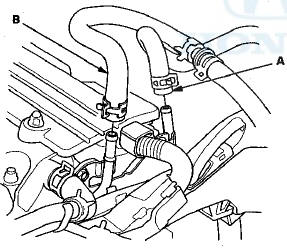
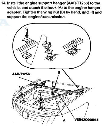
13. Attach the engine hanger adapter (VSB02C000015) to
the threaded hole in the cylinder head.
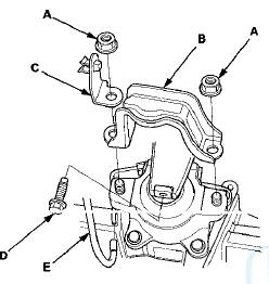
15. Remove the front engine mount stop nuts (A), the front engine mount stop (B), and the vacuum hose bracket (C), then remove the front engine mount bolt (D)r and disconnect the vacuum hose (E).
17. Remove the power steering line holder mounting bolts (A).
18. Remove the two heat shield bolts (A), the heat shield (B), and the two power steering gearbox mounting bracket bolts (C), then remove the power steering gearbox mounting bracket (D).
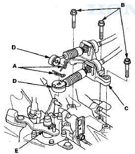
19. Remove the power steering gearbox stiffener bolts (A) and the power steering stiffener plates (B).
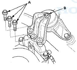
20. Remove the upper transmission mount bracket bolts (A).
NOTE: Do not remove the TORX bolt (B) from the upper transmission mount. If the TORX bolt is removed, the upper transmission mount must be replaced as an assembly.
21. Remove the three upper transmission mount bracket bolts (A), the upper transmission mount bracket (B), the ground cable mount bolt (C), and the ground cable (D).
22. Remove the upper transmission mount bolts (A).
23. Raise the vehicle on a lift, and make sure it is securely supported.
24. Remove the front wheels.
25. Remove the front splash shield.
26. Drain the MTF. Reinstall the drain plug using a new sealing washer (see page 13-5).
27. Remove the damper fork (see step 4 on page 18-31).
28. Separate the knuckle ball joint from the lower arm (see page 18-21).
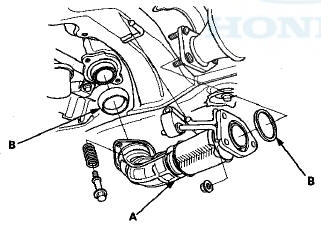
29. Remove exhaust pipe A and the gaskets (B).
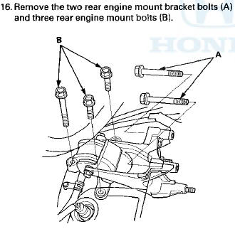
30. Remove the rear engine mount bracket bolts.
31. Remove the subframe mid mount bolts (A) and the subframe mid mount (B) from both sides.
32. Remove the lower transmission mount mounting nuts (A).
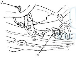
33. Remove the power steering line holder bolt (A) and the power steering line from the clamp (B).
34. Attach the subframe adapter (VSB02C000016) to the front subframe and hang the belt of the subframe adapter over the front of the subframe, then secure the belt with its stop.
35. Raise the jack and line up the slots in the subframe adapter arms with the bolt holes on the jack base, then securely attach them with four bolts.
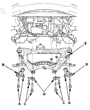
36. Remove the four front stiffener bolts (A), the front stiffeners (B), the four rear stiffener bolts (C), and the rear stiffeners (D), then remove the front subframe (E).
37. Remove the lower transmission mount bolts (A) and the lower transmission mount (B).
38, Pry the left drivechaft inboard joint (A) from the differential using a prybar.
NOTE: - Do not pull on the driveshaft, or the inboard joint may come apart. Pull the inboard joint straight out to avoid damaging the oil seal.
- Be careful not to damage the oil seal and the end of the inboard joint with the prybar.
39. Drive the inboard joint (A) of the right driveshaft off of the intermediate shaft using a drift punch and a hammer.
NOTE: - Do not pull on the driveshaft, or the inboard joint may come apart.
- Be careful not to damage the end of the inboard joint with the drift punch.
40. Remove the intermediate shaft (see page 16-22).
41. Remove the clutch cover (A) and the CKP sensor cover (B).
42. Securely support the transmission with a transmission jack.
43. Remove the lower transmission mounting bolts.
Front side
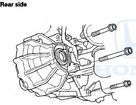
44. Pull the transmission away from the engine until the transmission mainshaft clears the clutch pressure plate.
45. Slowly lower the transmission about 150 mm (6 in).
Check once again that all hoses and harnesses are disconnected and free from the transmission, then lower it completely.
 Back-up Light Switch Test
1. Disconnect the back-up light switch 2P connector (A).
2. Check for continuity between back-up light switch 2P
connector terminals No. 1 and No. 2. There should be
continuity only when the shif ...
 Transmission Installation
Special Tools Required
- Engine Support Hanger, A and Reds AAR-T1256*
- Engine Hanger Adapter VSB02C000015*
- Subframe Adapter VSB02C000016*
- Subframe Alignment Pin 070AG-SJAA10S
*: Are availabl ...
See also:
Using the Remote Transmitter
Press the trunk release button for
approximately one second to unlock and open
the trunk.
...
Circuit Diagram
...
Driver and Passenger Safety
This section gives you important
information about how to protect
yourself and your passengers. It
shows you how to use seat belts. It
explains how your airbags work. And
it tells you how to ...