 Honda Accord: Transmission Installation
Special Tools Required
- Engine Support Hanger, A and Reds AAR-T1256*
- Engine Hanger Adapter VSB02C000015*
- Subframe Adapter VSB02C000016*
- Subframe Alignment Pin 070AG-SJAA10S
*: Are available through the Honda Tool and Equipment Program 888-424-6857.
NOTE: Use fender covers to avoid damaging painted surfaces.
1. Check the release bearing, and reinstall the release bearing and the release fork with the appropriate grease (see page 12-20).
2. Make sure the two dowel pins (A) are installed in the clutch housing.
3. Place the transmission on the transmission jack, and raise it to engine level.
4. Align the transmission mainshaft and the clutch pressure plate, then move the transmission inward until there is no gap between the transmission housing and the engine block.
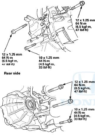
5. Install the lower transmission mounting bolts.
Front side
6. Install the clutch cover (A) and the CKP sensor cover (B).

7. Install the intermediate shaft (see page 16-28).
8. Install both driveshafts (see page 16-19).
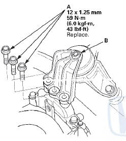
9. Install the lower transmission mount (A) with new bolts, then remove the transmission jack.
10. Support the front subframe with the subframe adapter (VSB02C000016) and a jack.
11. Position the steering gearbox washers (A) on the front subframe (B), and lift the subframe up to the body.
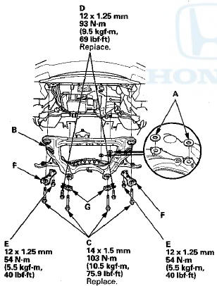
12. Loosely install new subframe mounting bolts (C), new rear stiffener mounting bolts (D), the front stiffener mounting bolts (E), the front stiffeners (F), and the rear stiffeners (G).
13. Partially tighten the right rear subframe mounting bolt (A); insert the subframe alignment pin through the positioning slot (B) on the rear stiffener, through the positioning hole (C) on the subframe, and into the positioning hole on the body, then tighten the subframe mounting bolt.
14. Partially tighten the left rear subframe mounting bolt in the same manner as in step 13.
15. Partially tighten the right and left front subframe mounting bolts.
16. Tighten the right rear mounting bolt to the specified torque with the subframe alignment pin in the positioning hole.
17. Tighten the left rear mounting bolt to the specified torque with the subframe alignment pin in the positioning hole.
18. Tighten the right and left front mounting bolt to the specified torque.
19. Check that the positioning holes and slots are aligned using the subframe alignment pin.
20. Tighten the rear and front stiffener mounting bolts to the specified torque.
21. Remove the jack and subframe adapter.
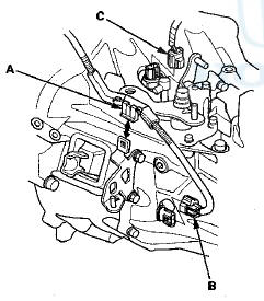
22. Install the power steering line holder bolt (A) and the
power steering line to the clamp (B).
23. Install the lower transmission mount mounting nuts.
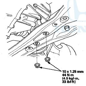
24. Install the subframe mid mount on both sides with
new bolts.

25. Install the rear engine mount bracket bolts with new bolts.
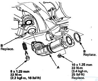
26. Install exhaust pipe A with new gaskets (B), the bolts, the springs, and new nuts as shown.
27. Connect the knuckle ball joint onto the lower arm (see page 18-21).
28. Install the damper fork (see step 4 on page 18-33).
29. Refill the transmission fluid to the proper level (see page 13-5).
30. Install the front splash shield.
31. Install the front wheels, and set them in the straight-ahead position.
32. Lower the vehicle on the lift.
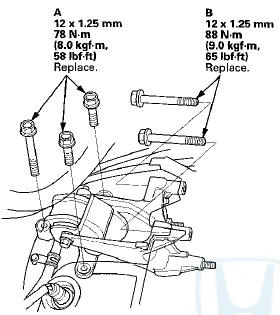
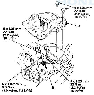
33. Install the upper transmission mount bolts (A).
34. Install the upper transmission mount bracket (A) with new bolts, and connect the ground cable (B) by installing its mounting bolt.
35. Install new upper transmission mount bracket bolts (A).
NOTE: - If the TORX bolt (B) was removed by mistake during removal, the upper transmission bracket must be replaced as an assembly.
36. Install the steering stiffener plates (A), and loosely tighten new power steering gear box mounting bolts (B) and the stiffener plate bolts (C).
NOTE: Make sure the lower washers placed in step 11 are correctly positioned before installing the bolts.

37. Install the power steering gearbox mounting bracket (A), and tighten the bolts to the specified torque, then install the heat shield (B).
38. Tighten the driver's side of the power steering gear box mounting bolts and the stiffener plate bolts to the specified torque alternately in two steps.
39. Install the rear power steering line holders (A).
40. Install three new rear engine mount bolts (A) and two new rear engine mount bracket bolts (B).
41. Install a new front engine mount bolt (A), the front engine mount stop (B), and the vacuum hose bracket (C) with new nuts, then connect the vacuum hose (D).
42. Remove the engine support hanger and the engine hanger adapter from the engine.
43. Install the evaporative emission (EVAP) canister hose (A) and the brake booster vacuum hose (B).

44. Install the strut brace (A) with the nuts (B), then install the hose to the clamp (C).
45. Install the bracket (A) and the harness clamp (B).
46. Install the harness clamp (A). Connect the output shaft (countershaft) speed sensor connector (B) and the back-up light switch connector (C).
47. Apply a light coat of silicone grease (P/N 08C30-B0234M) to the cable ends (A) and connect the cable end to the change lever assembly (B), then install the shift cable bracket (C) and the lock pins (D).
Do not bend or damage the shift cables.
NOTE: Make sure not to get any silicone grease on the terminal part of the connectors and switches, especially if you have silicone grease on your hands or gloves.
48. Install the under-hood fuse/relay box (A).
49. Apply a light coat of super high temp urea grease (P/N 08798-9002) to the end of the slave cylinder pushrod.
Install the slave cylinder and the bracket mounting nut. Be careful not to bend the clutch line.

50. Install the battery base (A) and the cable clamp (B).
51. Install the air cleaner assembly (see page 11-332).
52. Do the battery installation procedure (see page 22-92).
53. Install the front grille cover.
54. Check the wheel alignment (see page 18-5).
55. Check the shift lever and the clutch operation.
56. Test-drive the vehicle.
 Transmission Removal
Special Tools Required
- Engine Support Hanger, A and Reds
AAR-T1256*
- Engine Hanger Adapter VSB02C000015*
- Subframe Adapter VSB02C000016*
*: Are available through the Honda Tool and Equipme ...
 Transmission Disassembly
Exploded View-Clutch Housing
1.DIFFERENTIAL ASSEMBLY
2.SHIFT FORK ASSEMBLY
3.6 mm FLANGE BOLT
13 N-m (1.3 kgf-m, 9.4 Ibf-ft)
4.BEARING SET PLATE
5.COUNTERSHAFT ASSEMBLY
6.NEEDLE BEARING
7.OI ...
See also:
ATF Pump Inspection
1. Install the ATF pump drive gear (A), the driven gear
(B), and the ATF pump driven gear shaft (C) in the
main valve body (D). Lubricate all parts with ATF, and
install the ATF pump driven gear wi ...
TripMeter
The trip meter shows the number of
miles (U.S.) or kilometers (Canada)
driven since you last reset it.
There are two trip meters: Trip A
and Trip B. Switch between these
displays by pressing ...
HVAC Control Unit
Removal / Installation
1. Remove the audio unit (see page 23-115).'
2. Remove the self-tapping screws. If necessary, replace
the bulbs (A).
3. While holding the HVAC control unit (A), firmly press
the center of one of ...