 Honda Accord: System Diagnostic Mode
Start-up procedure and Diagnostic IVieny
There are two ways t o enter the diagnostic mode: Method 1 : Start the vehicle. When the globe screen appears, connect the SCS service connector (see page 23-237) to the navigation service connector located behind the navigation unit in the trunk. The screen changes to the System Links screen and automatically begins running the self diagnostic. See the System Links section for more information.
NOTE: When finished troubleshooting, make sure to remove the SCS service connector.
Method 2: Start the vehicle, and at the disclaimer screen use the navigation display hard buttons as described below: Make sure the battery is in good condition then press and hold the three buttons MAP/GUIDE, MENU, and CANCEL, for about 3 seconds. The display screen goes directly to the Select Diagnosis Items menu shown below.
• Self-Diagnosis Mode (runs the automatic diagnosis of the navigation system) • Detail Information & Setting (allows you to manually diagnose the navigation system)
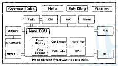
System Links
1. Enter this screen by connecting the SCS service connector or by selecting Self Diagnosis Mode from the navigation screen main menu. The message at the bottom of the screen flashes indicating the diagnosis is running. Make sure you enter the audio anti-theft code.
NOTE: • The system cannot complete a full diagnosis unless the engine is running.
• DTC 1501 and/or 2703 can be stored when the ignition switch is at ACCESSORY (I). With the ignition switch is in ACCESSORY (I), the climate control unit is turned off and the navigation unit loses communication and stores DTCs. Therefore, there is a possibility that the system is normal even though 2703 is stored. Check system links with the engine running, and if it appears normal, the system is OK at this time.
2. Rotate the Interface dial to select the Icon you want to diagnose. Push In the selector to see the details of that diagnostic function.
The System Links function runs automatically and displays a flashing message at the bottom of the screen reminding you to have the engine running for the test The diagnostic tests the following: • Most of the wires connecting the navigation components shown in the block diagram.
• The results from the various components shown in the block diagram.
• The microphone is tested by listening to the bong sound produced by the navigation unit from the speakers when the diagnosis is started. This requires that the audio system be operating normally.
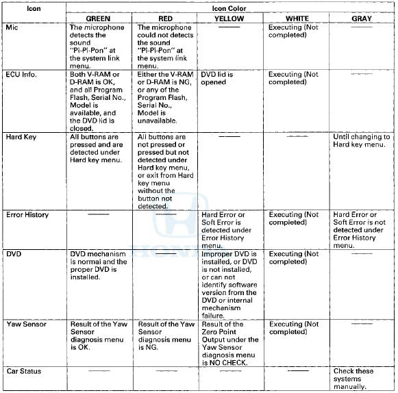
When the diagnosis finishes, the icons turn different colors based on their test status. The color definitions are shown below and can also be seen by selecting Help on the System Links screen.
The indication on the screen may not change until you exit and reenter the Self-Diagnosis mode. In some cases, you may have to restart the engine for the indication to change. After you repair the affected component or harness, repeat this diagnosis.
Each icon color is explained in the table.
NOTE: By selecting the HELP icon, you can see a description for each color.
Scon Color Information
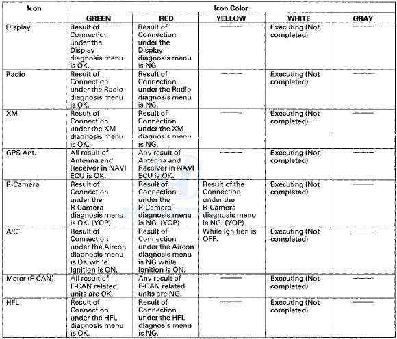
*: DTC 2703 can be stored when the ignition switch is in ACCESSORY (I). With the ignition switch in ACCESSORY (I), the climate control unit is turned off and the navigation unit loses communication and stores DTCs. It is possible that the system is normal with DTC 2703 stored. Check the system links with the engine running, and if it shows normal, the system is OK at this time.
Factory diagnostic screen In Line Diag
NOTE: If the vehicle left the factory in the factory diagnostic mode, you will see this screen every time you turn on the ignition. You may also see this screen if you recently replaced the navigation unit.
When a navigation unit is powered up for the first time at the factory, the factory diagnosis screen (In Line Diag) appears. Normally the factory does the steps necessary to verify proper operation and terminate the factory diagnosis.
Until the proper confirmation sequence is done, the screen appears every time the vehicle is started.
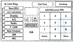
Follow the steps below to prevent the screen from showing up in the future: • Press and hold the buttons MENU, MAP/GUIDE, and CANCEL for about 3 seconds. The Select Diagnosis items screen appears.
• Press and hold the MAP/GUIDE button for 5 — 10 seconds. A screen with a Complete button, appears.
• Press complete, then Return, and then shut the key off for 5 seconds. Do not disconnect the battery during this period as the unit is saving the setting to the SRAM memory. The In Line Diag should not appear again.
• Restart the vehicle, and confirm normal operation by completing the TQI of the Navigation System Service Bulletin.
Detailed Information & Settings
These sections allows you to run a specific diagnosis and allows additional setting choices for some screens that are not shown when selecting an icon from the System Links screen.
When you select the menu item Detail Information & Setting menu, the main diagnosis menu is displayed.
Monitor Check
Overview of navigation display unit • The navigation display unit communicates with the navigation unit over its own GA-Net bus. Information sent by the navigation unit to the navigation display unit includes commands to control the LCD back light.
• The security system protects the navigation display unit by daisy-chaining the security signal through it, and then passing the signal to the audio unit.
• The illumination input from the gauge brightness control provides back lighting for the buttons surrounding the screen.
These screens allow you to troubleshoot the navigation display unit. Select the item you want to troubleshoot, and follow the diagnostic instructions.
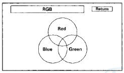
RGB Color
This screen verifies that the navigation display unit is receiving the video (R, G, B and Composite sync) signals properly. The three primary colors should all appear without distortion. The combination of all three should produce a central white section. If any of the colors are missing, troubleshoot for the color signal (see page 23-219). Ifthe picture has lines in it or scrolls horizontally, or vertically, troubleshoot for a Composite sync problem (see page 23-221).
Gray Tone
This screen diagnoses problems with contrast. You should be able to see the changes from bar to bar across the scale. It is normal for the two bars on either side to appear the same. If you can't see changes from bar to bar, replace the navigation display unit.
Black Raster
This diagnostic screen checks for pixels that may be stuck on. The entire display must be black. If pixels are stuck on, replace the navigation display unit.
Color Pattern
The chart below shows the colors being used for the map and menu screens. This is for factory use only. To check the color signal, use the RGB Color diagnostic found under the Monitor Check.
White Raster
This diagnostic screen checks for pixels that may be dead (off). The entire display must be white. If there are dead pixels, replace the navigation display unit
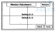
Monitor Adjustment
This allows you to center the navigation d^p!В«y. UsВ© the interface dial to move the picture up/down or left/right. It is unlikely that you will ever need to adjust the monitor position. The Default button will reset the display position to factory specifications.
Unit Check (Quick Check)
Some of the tests and screens that are displayed under the Unit Check are different from the more detailed checks listed in other areas.
To start the test, select the item you want to check.
Display
• Radio
• GPS
• ECU Info.
• Rear Camera
• PC Card Info.
• Hard Key
• Yaw Sensor
•DVD
•Aircon
• HFL
• XM
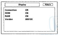
Display
This diagnosis does additional checks on the communication bus between the navigation unit and the navigation display unit. In addition, this test checks the internal electronic functions.
• When the connection is NG, first check for loose terminals at the navigation unit and the navigation display unit connections. Next check for an open or short in the ECU Bus line between the navigation unit and the navigation display unit. If the line has an open or short, replace the affected shielded harness.
• If the ROM or RAM is NG, replace the navigation display unit.
• The version represents the software version in the display.
Radio
If NG is indicated, check for loose audio unit connectors.
NOTE: Ifthe XM link appears red, but the radio link appears green in the navigation system link, refer to audio system symptom troubleshooting.
GPS
If GPS indicates NG (ANT), then check the entire GPS antenna wire from the navigation unit to the GPS antenna. If the wire is crushed or damaged, try a known-good GPS antenna. Ifthe diagnosis then reads OK, replace the original GPS antenna. If the diagnosis still reads NG (ANT), replace the navigation unit.
Select information to see the GPS satellite details.
ECU info.
This screen looks for problems in the navigation unit When you initiate this diagnosis, the navigation unit may freeze or delay up to a minute while the diagnosis runs.
NOTE; Do not try to end this diagnosis by pressing OK or Mem clear before it finishes, otherwise the system may reboot.
• If V-RAM or D-RAM is NG, replace the navigation unit • DVD lid displays the state of DVD Lid of navigation unit.
• Program Flash; Displays the version of the navi software in memory.
• Program on DVD: If displayed, this value represents the version of the navigation software on the navigation DVD.
• DVD version represents the database version on the DVD. You can find this information in either the Setup Screen Version, or in the Diagnostic Screen Version.
• Serial No. should be the same as the serial number found on the underside of the navigation unit. You need this number to obtain the security code f r om the . Interactive Network (iN) system.
• The Mem Clear is for factory use and should not be used unless instructed by the factory.
Selecting this will clear the customer's settings, personal information, GPS orbital data, and anything else stored in memory.
Rear Camera (Optional)
• If the optional rearview camera is connected, it will be displayed as OK.
• It displays OFF when the optional rearview camera is not connected.
PC Card info.
There is no PC Card in the PC slot, and the screen should display, PC Card is not inserted.
NOTE: Do not insert any card or object into the slot.
If the factory provides a PC card and instructs you to insert it, the screen displays the Manufacturer, and Product Name as shown in the following screen.
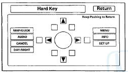
Hard Kef
This diagnostic tests the interface dial and the buttons that surround it. For this model, the interface dial and buttons do not use the GA-Net bus for communications.
To complete the test, touch each button on the vehicle's audio switch panel, and move the interface dial to each indicated position. As each function is tested, the corresponding button on the display should highlight.
To exit, push in and hold the selector knob.
NOTE: You cannot use the onscreen return button to exit this function
Yaw Sensor
This screen gives a quick test of the yaw sensor functionality based on the two voltages Sensor and Offset. For more information see the Yaw Rate diagnosis.
DVD
This diagnosis tests the navigation DVD reader.
NOTE: If this test fails, remove the navigation DVD, clean it, and retest before ordering a new DVD.
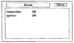
Aircon
This diagnostic tests the climate bus connection (AC-SI and AC-SO) between the navigation unit and climate control unit. Make sure the engine is running for this test.
NOTE: If this test is run with the ignition switch is in ACCESSORY (I), the result will be NG.
HFL
This checks the 4 wire communication bus between the HandsFreeLink control unit and the navigation unit.
XM
• This checks the GA-NET Bus line to the XM receiver.
• When connection is shown with NG, check the connection between XM receiver and audio unit.
Functional Setup
Select the item you want to check
• Save Users Memory
• Demo Mode
• Mic Level
Save Users Memory
When replacing the navigation unit, this function allows the dealer to transfer the customer's personal data to the new navigation unit. The transferred information includes their Setup settings, and personal addresses.
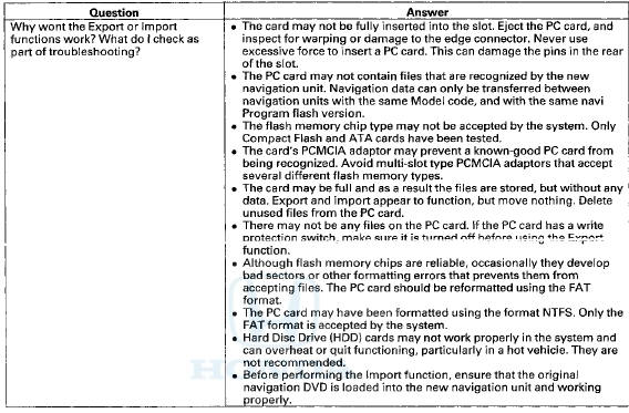
The dealer inserts a PC card to the navigation unit, and then selects the Save Users Memory function. The two functions in this diagnostic screen are EXPORT and IMPORT. EXPORT saves the customer's data to the PC card, and IMPORT moves the PC card files to the new navigation unit.
Before starting this function, see the PC Card FAQs for information regarding PC cards, and how to use this function.
1. Select the EXPORT button to move the customer's data from the original navigation unit to the PC card.
Select YES on the Export User Data Confirmation screen. The process takes only a couple of seconds.
The system stores two files on the card.
NOTE: ifthe EXPORT button is grayed out, check the PC card's edge connector, and the pins inside the navigation unit (with a flashlight) for damage.
2. After installing the customer's original DVD in the new navigation unit, allow the system to boot up.
Insert the PC card in the new navigation unit and enter the Save Users Memory in the navigation system diagnostic mode.
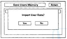
3. Select the IMPORT button to move the two files stored by the Export process from the PC card to the new navigation unit. Select YES on the Import User Data Confirmation screen. When the transfer is finished (a few seconds) the system automatically reboots. After the system reboots, remove the PC card from the PC card slot.
NOTE: If the IMPORT button is grayed out, check if the Model and the Program Flash shown on the Version screen are the same for the two navigation units.
Demo Mode
This screen is for factory use only, and should always be set to OFF. Occasionally the DEMO setting is turned ON when vehicles are being used at Auto Shows or similar events. Turning this feature on, allows the navigation system to automatically follow a route to a destination when the vehicle is stationary. The Speed Rate changes the speed of the demo mode.
Mic Level
This diagnostic allows you to independently test the microphone and the navigation TALK and BACK buttons. They are used to activate the voice control system. The microphone is located near the map light in the roof console. The microphone can now isolate the driver's voice even when there is noise or other conversations in the vehicle. To properly check the microphones, make sure you are sitting in the driver's seat.
• Press the navigation TALK button on the steering wheel, wait unit you hear a beep, and in a normal voice say "testing". The TALK indicator on the screen should momentarily turn green, and the text Now Recording... should appear in yellow. If the talk indicator shown on the screen does not briefly turn green, check the wiring from the steering wheel navigation TALK button to the navigation unit. If there is no Mic Level movement when you speak, then you should check the wires running from the microphone in the roof console to the HandsFreeLink control unit and the navigation unit. If the wires are OK, the microphone must be faulty; replace the microphone located in roof console (see page 23-240).
• Press the navigation BACK button on the steering wheel. This should cause the Cancel indicator on the screen to momentarily turn green. If it does not briefly turn green, check the wiring from the steering wheel navigation BACK button to the navigation unit.
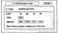
F-CAN System Link
F-CAN (Fast Controller Area Network) passes i n f o r m a t i o n between processors o n t h e network. The F-CAN n e t w o r k uses a c o m m u n i c a t i o n protocol that t r a n s m i t s data at 500 Kbps.
• I f t h e diagnostic screen b e l o w reads NG w i t h t he i g n i t i o n s w i t c h is in ON (II), t h e n diagnostic t r o u b le codes (DTCs) f o r t h e F-CAN can be retrieved w i t h the HDS (Honda Diagnostic System). The data displayed in t h e ID boxes is irrelevant.
• For more details on troubleshooting the F-CAN, refer t o t h e m u l t i p l e x integrated control system and the PGM-FI system.
GPS Information
This screen s h o w s t h e current status of GPS reception.
The circular d i a g r am shows t h e current location of t he GPS satellites ( y e l l ow numbers) as t h e y w o u l d appear in t h e sky. The outer c i r c le represents t h e horizon (0 degrees elevation). The m i d d l e and inner circles represents 30 a n d 60 degrees respectively. The very center of t h e d i a g r am (90 degrees elevation) is d i r e c t ly overhead. Nearby o b s t r u c t i o n s , like tall b u i l d i n g s w i ll block satellites in t h a t d i r e c t i o n . That is w h y it is necessary t o be in an open area t o effectively t r o u b l e s h o o t GPS reception issues. The satellite numbers s h o w n o n t h e d i a g r am correspond t o t h e PRN number in t h e GPS Details screen. There are always at least 24 active GPS satellites in o r b i t . Because satellites f a i l , a n d have t o be r e m o v e d f r om service, spares are always parked in orbit,ready to be activated. This is w h y t h e PRN (satellite ID number) can be greater t h a n 24.
NOTE: W h e n y o u use t h i s screen f o r t r o u b l e s h o o t i n g, park t h e v e h i c l e outside, away f r om b u i l d i n g s , t a l l trees, and high-tension w i r e s f o r at least 10 m i n u t e s w i t h the engine r u n n i n g.
• The Number of Satellites box shows t h e number of - acquired satellites ( m a x i m um of 12). It s h o u l d contain t h r e e or m o r e icons, if not, t r o u b l e s h o o t f o r GPS icon is w h i t e or not s h o w n (see page 23-225).
• The Current Position shows latitude, l o n g i t u d e , and e l e v a t i o n (in feet). If t h e r e are less t h a n f o u r satellites, t h e elevation can be g r o s s l y inaccurate.
• The Date/Time f i e ld shows t h e current date, a n d also a t i m e that includes daylight savings and other offsets entered b y t h e customer in Setup screen 2 Adjust Time Zone/Clock.
NOTE: Pressing t h e map/guide b u t t o n displays t he satellite number o n each circle.
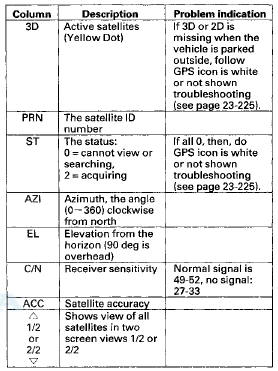
GPS Detail
By pressing and holding the MENU button for 2 seconds, a GPS Detail screen appears. This screen displays real time incoming satellite positional data when the vehicle is outside in the open. The information shown on this screen is for factory use.
NOTE: The date shown in an example only.
• The box TS/AS and H Dop/V Dop is for factory use.
• The Speed and Direction information is updated in real time when driving.
• The Date/Time Information is the same as in Setup screen 2 Adjust Time Zone/Clock.
• If the 3D icon is shown above the yellow dots, this implies that at least four satellites are available for map positioning, and the GPS indicator on the map screen will be green. See the Global Positioning System detailed explanation in the System Description.
• If the row of data in the table below begins with a yellow dot, the AZI and EL fields can be used to locate each satellite on the circular GPS diagram (see prior screen).
NOTE: The table of values define the terms at the top of the columns in the GPS Detail screen.
Yaw Rate
This diagnosis checks the yaw rate sensor in the navigation unit. This device detects when the vehicle turns, and repositions the vehicle position icon on the map screen. For more detailed information, see the yaw rate sensor theory of operation under System Description {see page 23-150).
• Sensor indicates the voltage output from the yaw rate sensor. It should indicate about 2.500 V when the vehicle is stopped.
• Offset is the reference voltage or standard within the yaw rate sensor. It also should indicate about 2.500 V when the vehicle is stopped.
• A sensor output voltage LOWER than the Offset voltage indicates that the vehicle is turning to the right A sensor output voltage HIGHER than the Offset voltage indicates that the vehicle is turning to the left.
• The yaw rate offset, and sensor should both indicate about 2.500 V when the vehicle is stopped. If either reads zero, or 5.000 V, replace the navigation unit.
• The yaw rate offset and sensor should be within +/—0.01 V of each other when the vehicle is stopped.
The sensor value should change relative to the offset as the vehicle turns while driving. If not, replace the navigation unit.
Example: Vehicle stopped
Normal
Offset 2.526 V
Sensor 2.516-2.536 V
Abnormal
Offset 2.526 V
Sensor 2.623 V
Example: Vehicle turning
Normal
Offset 2.526 V
Sensor 2.678 V (left turn)
2.478 V (right turn)
Abnormal
Offset 2.526 V
Sensor 2.623 V
(no change on turns)
• Sensitivity study represents the status of the internal tuning function. At initialization, this value starts at 6 and increases to 10 as the internal correction values become more accurate.
• The settings CCW Cal Factor, CW Cat Factor, and Set are for factory use only. THIS SHOULD NEVER BE ADJUSTED.
• For detailed analysis of the yaw rate select tuning.
Yaw Rate Tuning
This diagnosis allows you to graphically display problems with the yaw rate sensor.
• The ANG-Disp value accumulates any differences between the offset and sensor voltages (see Yaw Rate diagnosis). When the sensor functions properly, the random changes in these two voltages generally cancels out, so the value is 0. However if one voltage is consistently higher than the other, then the ANG-Disp value accumulates the constant change.
• The Reset button temporarily clears the angular accumulation (ANG-Disp), and clears the display dots.
• Do not touch the CCW, CW, or Set buttons. These are used for factory setup only.
Two tests are explained. For large problems with the sensor values, the stationary test usually confirms whether the sensor is defective. For yaw rate issues related to driving, do the road test.
1. Stationary test: If the VP icon spins in place and the ANG-Disp value slowly increases or decreases in value, the yaw rate sensor is defective. Replace the navigation unit.
2 . Road test: Drive the vehicle on a very straight road.
Enter the diagnostic mode, select Yaw rate, and touch the Tuning button. While driving down a straight road, the white dots should trace a straight line across the screen. However, if you are driving on a straight road, and you notice the dots constantly dropping down or heading up as you drive, the navigation unit's yaw sensor is defective. You can touch Reset to clear ANG-Disp, and dotted lines.
If either test above fails, please enter Yaw rate sensor defective for the problem description, on the Navigation core return form.
NOTE: The CCW, CW and Set buttons are disabled and cannot be activated.
Car Status
Use this screen to confirm that the navigation unit is properly receiving input signals. Signals equal to (0) are OFF, and signals equal to (1) are ON. If the value on the display does not match the actual vehicle status, then check the wire carrying the signal.
• VSP-Vehicle Speed Pulse from ECM/PCM (Connector A (8P) terminal No.6)
a) OFF (0) when vehicle is not moving
b) ON (1) when vehicle is moving
The VSP comes from the ECM/PCM as a dedicated signal. Internally, the navigation unit compares the actual VP on the map against street data to adjust the pulse to speed scaling factor. As this scaling factor becomes more accurate, the Level gradually increases from 0 to 10 (see the Tire Calibrate diagnostic screen).
• BACK-Reverse indication from taillight relay
(Connector A (8P) terminal No.5)
a) OFF (0) when the shift lever is in any position other than reverse
b) ON (1) when the shift lever is in reverse
The Back signal is used by the navigation unit to allow the map screen to show the VP moving backwards when in reverse. This signal is needed because the Speed Pulse has no direction indication.
• IGNITION-Ignition Switch Position Indication {Connector A (8P) terminals No. 1 and 2) Detects i f t he engine is running is running using information provided over the F-CAN bus.
a) OFF (0) when the ignition switch position is in ACCESSORY (I) b) ON (1) when the ignition switch position is in ON (II)
• ILL-lilumination Indication (Connector B (32P) terminal No. 5) a) OFF ( 0 ) when parking lights, or headlights are off b) ON (1) when parking lights, or headlights are on
The navigation uses the signal to determine whether to put t h e navigation screen into the Day or Night brightness mode. (Setup screen 1) • ILL CANCEL
This item detects whether the illumination cancel function is in use.
a) OFF ( 0 ) if illumination cancel is not selected
b) ON (1) if illumination cancel is activated
The illumination cancel function is activated by increasing the dash brightness to MAX. The F-CAN bus passes this information from the gauge control module to the navigation unit.
NOTE: This setting is unaffected by the display mode hard button located below and to the left of the interface dial.
Version
This screen displays the current version information for the navigation system software. In addition, this screen allows the loading of updated software if requested by the factory, or instructed by a Service Bulletin, Software may be loaded from a CD o r a PC card.
• Program Flash: Displays the version of the navigation software in memory.
• Program Disc: If displayed, this value represents the version of the navigation software on the navigation DVD.
NOTE: The last two letters of the Program Flash or DVD fields indicate which DVD is installed in the unit The letters KA imply that a United States DVD is installed. Ifthe letters are KC, then a Canada DVD is installed. (See coverage discussion below.) • IPL, APL, DBOOT, and System uCom, are all for factory use.
• Model: For this model, the field should begin with TAO.
• Download: Do not touch, unless instructed by the factory.
Check any official Honda service website for more service information about navigation DVDs.
There are two navigation DVDs produced for this model.
• The white DVD labeled United States is for the US market and contains maps for the contiguous 48 US states, and some southern portions of Canada.
Customers wanting additional northern coverage in Canada, can purchase a Canada DVD by contacting the DVD fulfillment desk.
• The gray DVD labeled Canada, is for the Canada market, and contains maps for all of Canada, plus some of the northern US states. If customers with this DVD require full US coverage {including states like Florida and Texas), they may purchase a United States DVD by contacting the DVD fulfillment desk.
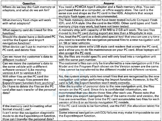
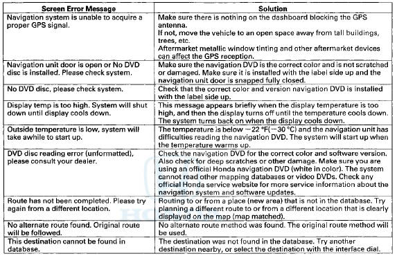
PC Card FAQs
Error Message Table
 Circuit Diagram
...
 DTC Troubleshooting
DTC 1001: FROM System info Error
NOTE:
• Check the vehicle battery condition first (see page
22- 9 0 ) .
• Before you troubleshoot, make sure to follow the
General Troubleshooting Inf ...
See also:
Passenger's Under-dash Fuse/Relay
Box (MICU) Removal and
Installation
NOTE: SRS components are located in this area. Review
the SRS component locations 4-door (see page 24-21),
2-door (see page 24-23), and precautions, and
procedures (see page 24-25) before doing rep ...
Ball Joint Boot Inspection / Replacemen
Special Tools Required
- Clip Guide, 45 mm 070AG-SJA0300
-Clip Guide, 41 mm 07974-SA50700
1. Check the ball joint boot for weakness, damage,
cracks, and grease leaks.
NOTE:
- If the ball joint ...
Symptom Troubleshooting
Rapid brake pad wear, vehicle vibration
(after a long drive), or high, hard brake pedal
NOTE: Make sure that the caliper pins are installed
correctly. Upper caliper pin B and lower caliper pin A ar ...