 Honda Accord: System Description
SRS Components
Airbags
The SRS is a safety device which, when used with the seat belt, is designed to help protect the driver and front passenger in a frontal impact exceeding a certain set limit. The system consists of the SRS unit, including safing sensor and impact sensor (A), the cable reel (B), the driver's airbag (C), the front passenger's airbag (D), side airbags (E), side curtain airbags (F), seat belt tensioners (G), side impact sensors (first) (H), front impact sensors (I), rear safing sensor (J), and side impact sensors (second) (K).
Since the driver's and front passenger's airbags use the same sensors, both normally inflate at the same time. However, it is possible for only one airbag to inflate. This can occur when collision severity is near the threshold for airbag deployment. In such case, the SRS system will only deploy airbags when the protection provided by the seat belt is insufficient.
Front Passenger's Weight Sensors
The front passenger's weight sensors (L) are part of front passenger's seat. The front passenger's weight sensors detect the weight on the seat, and send the information to the ODS unit (M). If the total weight is about 65 lbs (30 kg) or less, the ODS unit sends a signal to the SRS unit to prevent the passenger's airbag from deploying. When the passenger's airbag is disabled, the passenger airbag cutoff indicator (N) on the center panel comes on to alert the driver that the front passenger's airbag will not deploy in a front-end collision.
NOTE: The sensors only detect the weight on the seat. The sensors do not detect the weight of the passenger's legs or arms that may be resting on the floor or armrests.
Driver's Seat Position Sensor
The driver's seat position sensor (0) is under the driver's seat on the left side. When the driver's seat is moved to forward most position, the deployment of the driver's airbag is moderated to decrease its force of impact during a front-end collision.
4-door shown; 2-door is similar.
Rear Safing Sensor
The rear safing sensor is located under the rear seat cushion. The rear safing sensor performs the same basic function as the safing sensor in the SRS unit. It measures sideways G force, such as the force the vehicle would receive in a side collision in the rear, and sends that information to the SRS unit. The SRS unit uses that information, and the information from the second side impact sensors to determine the side that is impacted and the force. Ifthe threshold is met, the SRS unit deploys the side airbag, the side curtain airbag and the seat belt tensioner on that side.
Side Airbag Cutoff Indicator/OPDS Operation
The indicator comes on when the front passenger's seat is occupied by a small adult or child who is leaning into the deployment path, or when an object (grocery bag, briefcase, purse, etc.) is in the seat. This indicates the passenger's side airbag is off and will not deploy; there is no problem with the side airbag. Ifthe passenger sits upright or moves to another seat, or you remove the object from the seat, the light should go off. There will be some delay between the occupant's repositioning, and when the indicator will turn on or off.
Passenger's Airbag Cutoff Indicator/Front Passenger's Weight Sensor Operation
The indicator comes on ifthe weight on the front passenger seat is about 65 lbs (30 kg) or less. This indicates the passenger's front airbag is off and will not deploy. The front airbag is shut off to reduce the chance of airbag-caused injuries.
SRS Operation
The main circuit in the SRS unit senses and analyzes the force of impact and, if necessary, ignites the inflator charges. If battery voltage is too low or power is disconnected due to the impact, the voltage regulator and the back-up power circuit will keep voltage at a constant level.
For the SRS to operate:
Seat Belt Tensioners
(1) A front impact sensor, side impact sensor, or the rear safing sensor must activate and send electric signals to the microprocessor.
(2) The microprocessor must compute the signals and trigger the tensioners.
(3) The charges must ignite and deploy the tensioners.
Driver's and Front Passenger's Airbag(s)
(1) A front impact sensor must activate and send electric signals to the microprocessor.
(2) The microprocessor must compute the signals, and trigger the airbag inflators.
(3) The triggered inflators that received signals must ignite and deploy the airbags.
Side Airbag(s)
(1) A side impact sensor must activate and send electric signals to the microprocessor.
(2) The microprocessor must compute the signals and trigger the side airbag inflators. However, the microprocessor does not trigger the front passenger's side airbag ifthe SRS unit determines that the front passenger's head is in the deployment path of the side airbag.
(3) The triggered inflators the signal must ignite and deploy the side airbags.
Side Curtain Airbag(s)
(1) A side impact sensor or the rear safing sensor must activate and send electrical signals to the microprocessor.
(2) The microprocessor must compute the signals and trigger the side curtain airbag and side airbag inflators.
(3) The triggered inflators that must ignite and deploy the side curtain airbag and side airbag at the same time.
4-Door
Self-diagnostic System
A self-diagnostic circuit is built into the SRS unit; when the ignition switch is turned to ON (II), the SRS indicator comes on and goes off after about 6 seconds if the system is operating normally. If the indicator does not come on, or does not go off after 6 seconds, or comes on while driving, it indicates a problem in the system. The system must be inspected and repaired as soon as possible.
For better serviceability, the SRS unit memory stores a DTCs related to the cause of the malfunction. The SRS unit is connected to the data link connector (DLC). This information can be read with the HDS when it is connected to the DLC (see page 24-36).
NOTE: Before you disconnect the negative cable from the battery for troubleshooting, refer to Battery Terminal Disconnection and Reconnection (see page 22-91).
2-Door
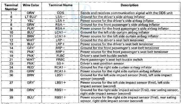
SRS Unit Inputs and Outputs at Connector A (39P)
Wire side of female terminals
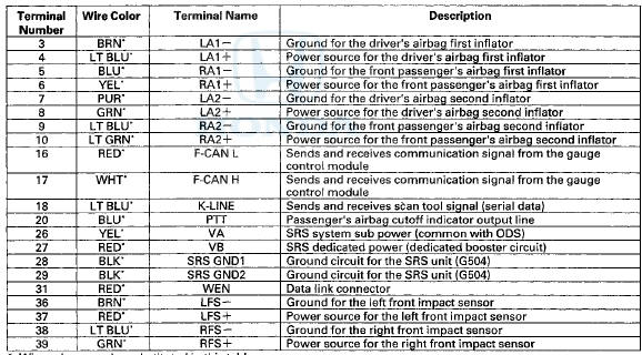
*: Wire colors may be substituted in this table.
SRS Unit Inputs and Outputs at Connector B (33P)
4 Door
Wire side of female terminals
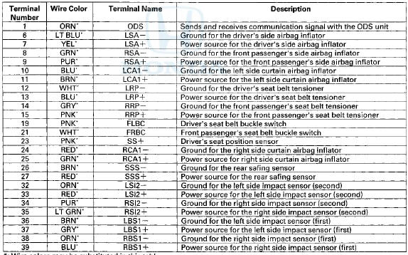
*: Wire colors may be substituted in this table.
SRS Unit Inputs and Outputs at Connector B (39P)
2-Door
Wire side of female terminals
*: Wire colors may be substituted in this table.

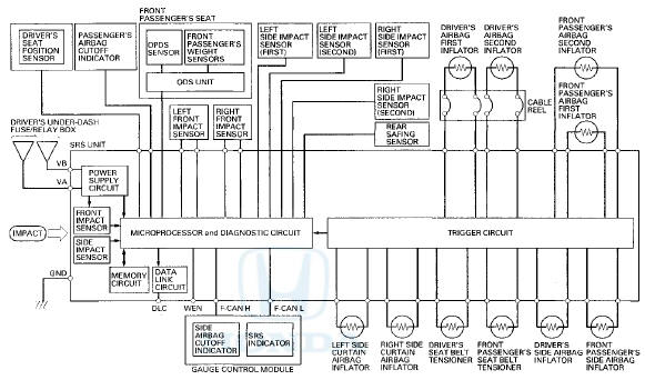
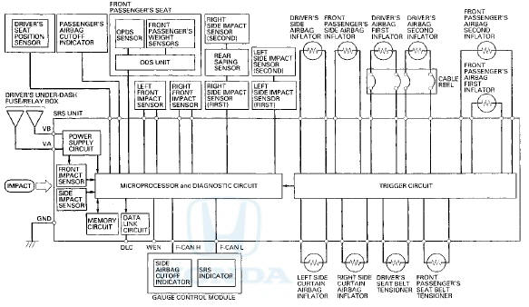
 Circuit Diagram
4-Door
4-Door
2-Door
2-Door
...
See also:
A/C Service Tips and Precautions
• Compressed air mixed with the R-134a forms a
combustible vapor.
• The vapor can burn or explode causing serious
injury.
• Never use compressed air to pres ...
Driver's Power Window Motor Test
Motor Test
1. Remove the power window master switch.
• 4-door (see page 22-305)
• 2-door (see page 22-306)
2. Test the motor in each direction by connecting battery
power and ground t ...
Brake System
• Parking Brake
Use the parking brake to keep the vehicle stationary when parking.
To apply:
Pull the lever fully up without pressing the
release button.
To release:
1. Pull the lever sli ...