 Honda Accord: System Description

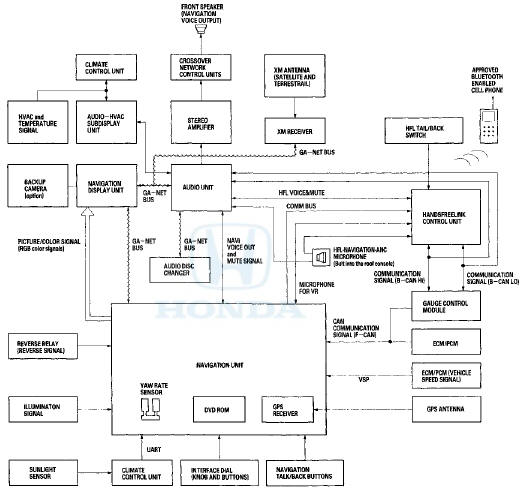
The navigation system is a highly-sophisticated, hybrid locating system that uses satellites and a map database to show you where you are and to help guide you to a desired destination.
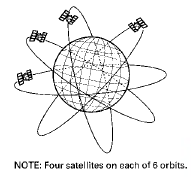
The navigation system receives signals from the global positioning system (GPS), a network of 24 satellites in orbit around the earth. By receiving signals from several of these satellites, the navigation system can determine the latitude, longitude, and elevation of the vehicle. In addition, signals from the system's yaw rate sensor and the ECM/PCM (vehicle speed pulse) enable the system to keep track of the vehicle's direction and speed of travel.
This hybrid system has advantages over a system that is either entirely self-contained or one that relies totally on the GPS. For example, the self-contained portion of the system can keep track of vehicle position even when satellite signals cannot be received. When the navigation system is on, the GPS can keep track of the vehicle position even when the vehicle is transported by ferry- The navigation system applies all location, direction, and speed information to maps and calculates a route to the destination entered. As you drive to that destination, the system provides both visual and audio guidance.
This navigation system also has voice recognition that allows voice control of most of the navigation functions. The Navigation TALK and BACK buttons on the steering wheel activate the voice control. The voice control also allows control of the audio and climate functions. The max brightness signal is passed to the navigation unit through the F-CAN bus.
The illumination signal (headlights ON) is used by the navigation unit to automatically switch the display between Night and Day brightness modes. When the gauge control module brightness control is set to max brightness, the navigation system stays in the day mode, even with the headlights on.
The GA-NET II communication bus passes information back and forth between the navigation display unit, the navigation unit and the audio system. The information passed on this bus is audio settings directed by the navigation unit.
The Comm. Bus connects the HFL, and navigation units. This bus supports these functions: •The navigation unit sends a POI phone number (on the Calculate route to screen) to the HandsFreeLink control unit for dialing.
• The navigation system could download the cellular phone book and call phone numbers in the book.
• The navigation unit can sense the status of a phone that is paired to the HFL.
System Diagram
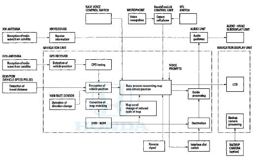
Navigation Function
The navigation system is composed of the navigation unit, the ECM/PCM (vehicle speed pulse), the GPS antenna, microphone, the voice control switch, audio unit, and the audio-HVAC subdisplay unit.
Function Diagram
GA-Net Bus Configuration
The GA-Net bus passes audio and navigation commands throughout the navigation and audio components. These commands include navigation audio/XM selections by voice, and XM station and music title names. Because the entire bus is interconnected between components, an open or short in the GA-Net bus harness may cause any or all of these functions to become inoperative.
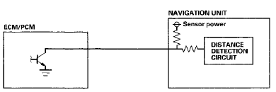
Vehicle Speed Pulse
The vehicle speed pulse is sent by the ECM/PCM. The ECM/PCM receives a signal from the outputshaft (countershaft) speed sensor, then processes the signal and transmits it to the gauge control module and other systems.
Yaw Rate-Lateral Acceleration Sensor
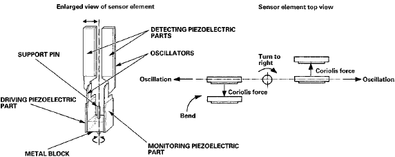
The yaw rate-lateral acceleration sensor (located in the navigation unit) detects the direction change (angular speed) of the vehicle. The sensor is an oscillation gyro built into the navigation unit.
Sensor Element Structure
The sensor element is shaped like a tuning fork, and it consists of the piezoelectric parts, the metal block, and the support pin. There are four piezoelectric parts: one to drive the oscillators, one to monitor and maintain the oscillation at a regular frequency, and two to detect angular velocity. The two oscillators, which have a 90-degree twist in the center, are connected at the bottom by the metal block and supported by the support pin. A detection piezoelectric part is attached to the top of each oscillator. The driving piezoelectric part is attached to the bottom of one oscillator, and the monitoring piezoelectric part is attached to the bottom of the other oscillator.
Oscillation Gyro Principles
The piezoelectric parts have electric/mechanical transfer characteristics. They bend vertically when voltage is applied to both sides of the parts, and voltage is generated between both sides of the piezoelectric parts when they are bent by an external force. The oscillation gyro functions by utilizing this characteristic of the piezoelectric parts and Coriolis force.
(Coriolis force deflects moving objects as a result of the earth's rotation.) In the oscillation gyro, this force moves the sensor element when angular velocity is applied.
Operation
1. The driving piezoelectric part oscillates the oscillator by repeatedly bending and returning when an AC voltage of 6 kHz is applied to the part. The monitoring-side oscillator resonates because it is connected to the driving-side oscillator by the metal block.
2. The monitoring piezoelectric part bends in proportion to the oscillation and outputs voltage (the monitor signal). The navigation unit control circuit controls the drive signal to stabilize the monitor signal.
3. When the vehicle is stopped, the detecting piezoelectric parts oscillate right and left with the oscillators, but no signal is output because the parts are not bent (no angular force).
4. When the vehicle turns to the right, the sensor element moves in a circular motion with the right oscillator bending forward and the left oscillator bending rearward. The amount of forward/rearward bend varies according to the angular velocity of the vehicle.
5. The detecting piezoelectric parts output voltage (the yaw rate signal) according to the amount of bend. The amount of vehicle direction change is determined by measuring this voltage.
Global Positioning System (GPS)
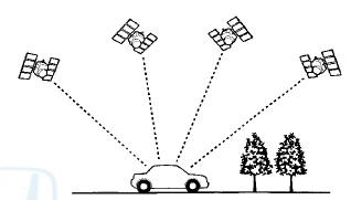
The global positioning system (GPS) enables the navigation system to determine the current position of the vehicle by using the signals transmitted from the satellites in orbit around the earth. The satellites transmit the satellite identification signal, orbit information, transmission time signal, and other information. When the GPS receiver receives a signal from four or more satellites simultaneously, it calculates the current position of the vehicle based on the distance to each satellite and the satellite's position in its respective orbit.
Position detection Image with GPS satellite
Precision of GPS
The precision of the GPS varies according to the number of satellites from which signals are received and the view of the sky. The acuracy is indicated by the color of the GPS icon shown on the display.

GPS Antenna
The GPS antenna amplifies and transmits the signals received from the satellites to the GPS receiver.
GPS Receiver and Clock
The GPS receiver is built into the navigation unit. It calculates the vehicle position by receiving the signal from the GPS antenna. The current time, vehicle position and signal reception condition is transmitted from the GPS receiver to the navigation unit to adjust vehicle position.
Navigation Unit
The navigation unit calculates the vehicle position and guides you to the destination. The unit performs map matching correction, GPS correction, and distance tuning. It also controls the menu functions and the DVD-ROM drive, and interprets voice commands. With control of all these items, the navigation unit makes the navigation picture signal, then it transmits the signal to the navigation display unit and audio driving instructions to the audio unit.
Calculation of Vehicle Position
The navigation unit calculates the vehicle position (the driving direction and the current position) by receiving the directional change signals from the yaw rate sensor and the travel distance signals from vehicle speed pulse (VSP) signal of the ECM/PCM.
Hap Watching Tuning
The map matching tuning is accomplished by indicating the vehicle position on the roads on the map. The map data transmitted from the DVD-ROM is checked against the vehicle position data, and the vehicle position is indicated on the nearest road. Map matching tuning does not occur when the vehicle travels on a road not shown on the map, or when the vehicle position is far away from a road on the map.
GPS Tuning
The GPS tuning is accomplished by indicating the vehicle position as the GPS's vehicle position. The navigation unit compares its calculated vehicle position data with the GPS vehicle position data. If there is large difference between the two, the indicated vehicle position is adjusted to the GPS vehicle position.
Distance Tuning
The distance tuning reduces the difference between the travel distance signal from the VSP and the distance data on the map. The navigation unit compares its calculated vehicle position data with the GPS vehicle position data. The navigation unit then decreases the tuning value when the vehicle position is always ahead of the GPS vehicle position, and it increases the tuning value when the vehicle position is always behind the GPS vehicle position.
Route Guidance
The navigation unit can calculate different routes to a selected destination. You have five options: • Direct Route —Calculate a route that is the most direct.
• Easy Route—Calculate a route that minimizes the number of turns needed.
• Minimize Freeways —Calculate a route that avoids freeway travel. If that is not possible, keep the amount of freeway travel to a minimum. This is not selectable (button grayed out) for trips greater than 100 miles.
• Minimize Toll Roads —Calculate a route that avoids, or minimizes travel on toll roads. This is not selectable (button grayed out) for trips greater than 100 miles.
• Maximize Freeways — Ca leu I ate a route that uses freeways as much as possible.
Audio Guidance
The navigation unit transmits audio driving instructions before entering an intersection or passing a junction. The audio instructions come through the audio unit to the front speakers.
NOTE: The front speakers are muted whenever the navigation system is giving guidance commands, and all of the speakers when the voice control system is being used.
Muting Signal Logic
The audio muting logic is orchestrated by the audio unit. The audio unit determines what audio source has priority to use the speakers.
The priority of the audio sources is as follows: HFL has the highest priority, followed by navigation, and finally the radio/CD-DVD player. The priority is passed by HFL to the audio unit by dedicated mute wires. The navigation mute signal is passed to the stereo amplifier.
The navigation unit temporarily disables the voice control buttons, but allows guidance to be heard. In addition, the audio unit suppresses the output from the audio unit, XM receiver, disc player, or other audio accessories.
When the navigation system sends out a voice route guidance command, the audio front speaker is muted, and the navigation voice is heard in the front speakers.
When the navigation voice control system is in use, all of the speakers are muted, and the navigation voice prompts are heard from the front speakers.
Solar Angle
The climate control unit uses the sun's angle, along with the sunlight sensor to control the driver/passenger A/C airflow.
Off load Tracking (bread-crumbs)
Off road tracking dots that can be followed on the map retrace your route back to a mapped (digitized) road.
Clock and Time Zone
The clock set up allows you to set daylight savings time, auto time zone and time adjustment.
DVD-ROM
The navigation DVD includes:
• Map Data
• Point of interest (POI)
• Navigation software
Audio Unit
The audio unit receives the voice guidance instructions from the navigation unit and transmits the instructions through the front speaker even when the audio system is in use. The audio unit also uses the HFL-navigation-ANC microphone signal to check the ANC output.
NOTE: If the navigation volume and/or voice feed back is turned off, this feature is disabled.
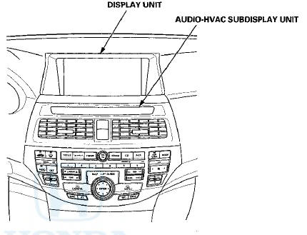
Display Unit
The display unit uses a liquid crystal display (LCD). The LCD is a 8-inch-diagonal, thin film transistor (TFT), strip type with 336,960 picture elements. The color film and fluorescent light are laid out on the back of the liquid crystal film.
Microphone (Mic)
Receives voice commands and transmits them to the navigation unit or HandsFreeLink control unit or active noise cancellation (ANC) for interpretation.
These systems share the same microphone.
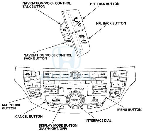
NAVIGATION TALK Button
Activates the voice control system in the navigation unit to accept voice commands.
NAVIGATION BACK Button
Returns the display to the previous screen (similar function as the CANCEL button).
Glossary
The following is a glossary of terms pertaining to the Voice Recognition Navigation System.

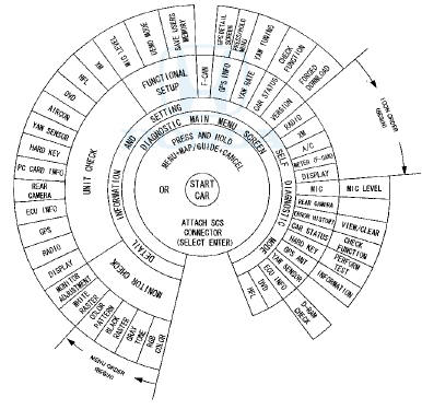
Diagnostic System Diagram
This diagram below shows all of the navigation diagnostic features available for system troubleshooting. The diagram starts at the center, and works outward in layers.
Access to the diagnostic features begins by starting the vehicle. This is necessary so the system can check the other systems connected by various busses. After starting the vehicle you can enter the diagnostic mode either by pressing and holding MENU, MAP/GUIDE, and CANCEL, or by connecting the 2-PIN SCS service connector.
The main menu screen allows 2 checking modes - one automatic, and one manual: • The automatic diagnostic check starts when you select "SELF DIAGNOSTIC MODE". The system runs for several seconds, and reports any issues with Red icons. Rotate the interface dial and select the icon you wish obtain the problem details.
• The manual diagnostic check is selected from the main menu by selecting "DETAIL INFORMATION AND SETTING".
The traditional diagnostic menu is displayed. This allows you to obtain additional details as instructed in the troubleshooting procedures.
NOTE: Do not clear or change settings unless specified by either the Service Manual troubleshooting procedures or by the factory. Otherwise, you may accidentally delete customer information, or remove the latest flash software version installed by the factory.
Navigation unit connectors
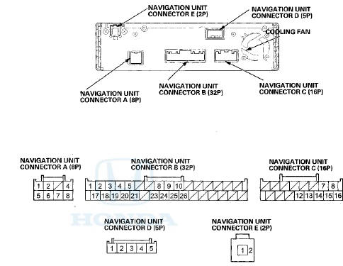
All connectors show wire side of female terminals
Front HFL-navigation-ANC microphone 7P connector
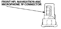
FRONT HFL-NAVIGATION-ANC MICROPHONE 7P CONNECTOR
wire side of female terminals
Navigation display unit 28P connector
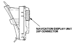
NAVIGATION DISPLAY UNIT 28P CONNECTOR
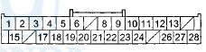
Wire side of female terminals
Interface dial 5P connector
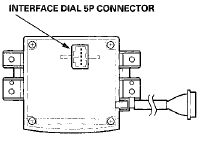
INTERFACE DIAL SP CONNECTOR

Wire side of female terminals
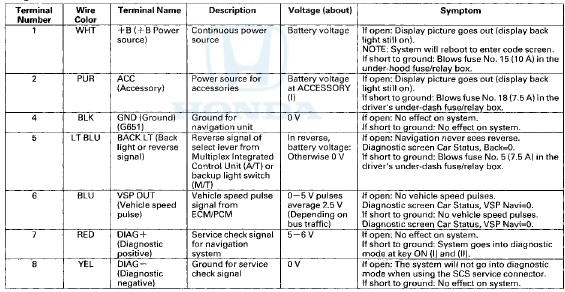
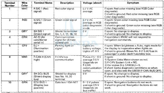
Navigation Unit Inputs and Outputs for Connector A (8P)

Wire side of female terminals
Navigation Unit Connector A (8P)
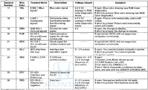
Navigation Unit Inputs and Outputs for Connector B (32P)
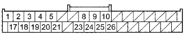
Wire side of female terminals
Navigation Unit Connector B (32P)
*The shielded wires have a heat-shrink tube insulating the outside of the wire.
The color of the insulating tube, typically black or dark gray, may not match the color of the wire shown on the circuit diagram.
Navigation Unit Connector i (32P)
* The shielded wires have a heat-shrink tube insulating the outside of the wire.
The color of the insulating tube, typically black or dark gray, may not match the color of the wire shown on the circuit diagram.
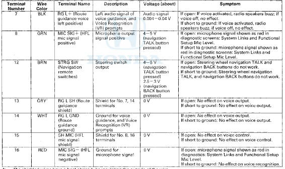
Navigation Unit Inputs and Outputs for Connector C (16P)
Wire side of female terminals
Navigation Unit Connector C (16P)
*The shielded wires have a heat-shrink tube insulating the outside of the wire.
The color of the insulating tube, typically black or dark gray, may not match the color of the wire shown on the circuit diagram.
Navigation Unit Inputs and Outputs for Connector D (5P)
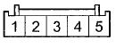
Wire side of female terminals
Navigation Unit Connector D (SP)
*The shielded wires have a heat-shrink tube insulating the outside of the wire.
The color of the insulating tube, typically black or dark gray, may not match the color of the wire shown on the circuit diagram.
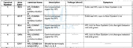
Navigation Unit Inputs and Outputs for Connector E (2P)

Wire side of female terminals
Navigation Unit Connector E (2P)
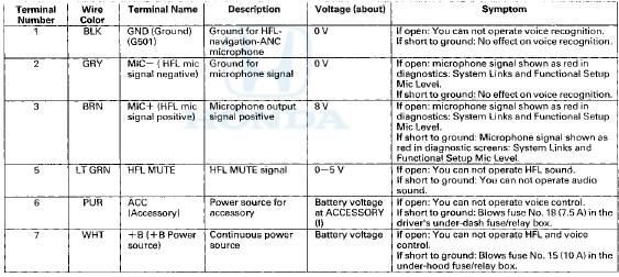
FRONT HFL-Navigation-ANC Microphone Inputs and Outputs for 7P Connector
Wire side of female terminals
Front HFL-Navigation-ANC Microphone IP Connector
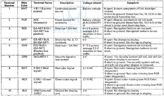
Navigation Display Unit Inputs and Outputs for 28P Connector
Wire side of female terminals
Navigation Display Unit 28P Connector
*The shielded wires have a heat-shrink tube insulating the outside of the wire.
The color of the insulating tube, typically black or dark gray, may not match the color of the wire shown on the circuit diagram.
Navigation Display Unit 28P Connector

* 1 : With optional rearview camera.
*2: The shielded wires have a heat-shrink tube insulating the outside of the wire.
The color of the insulating tube, typically black or dark gray, may not match the color of the wire shown on the circuit diagram.
Interface Dial Inputs and Outputs for 5P Connector
Wire side of female terminals
Interface Dial BP Connector
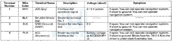
*The shielded wires have a heat-shrink tube insulating the outside of the wire.
The color of the insulating tube, typically black or dark gray, may not match the color of the wire shown on the circuit diagram.

 Circuit Diagram
...
See also:
Automatic Transmission and A/T Differential: (cont'd)
...
Multi-View Rear Camera
About Your Multi-View Rear Camera
The audio/information screen can display your vehicle’s rear view. The
display
automatically changes to the rear view when the shift lever is moved to (R.
T ...
Special Tools
...