 Honda Accord: System Description
Overview
The audio unit acts as the processor for all audio functions. You can select the audio functions from the front panel, the audio remote (on the steering wheel), or by using the navigation voice control system. The audio display provides the current front and rear audio status. For vehicles with navigation, additional audio information is available by touching the audio button. (See the owner's manual for more details.) The XM receiver and audio disc changer pass their signals is to the audio unit. In addition, they communicate with the audio unit via the GA-Net bus. Any open connections or short in the wiring in the GA-Net bus circuit will cause audio (including the audio accessories) and navigation functions to appear inoperative.
With the premium sound system, an audio amplifier unit powers the speakers, otherwise the speakers are powered directly by the audio unit.
The audio unit has a built-in EEPROM (electrically erasable programmable read-only memory). This memory holds the audio preset data (AM/FM radio frequency, sound settings) even when the battery power is removed.
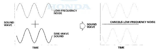
Active Noise Cancellation (ANC) system
The audio system is equipped with the ANC circuit in the audio unit.
The ANC system works to cancel engine booming sound up to about 2,000 rpm. The audio unit receives the engine speed pulse (NEP) from the ECM/PCM and outputs a sine-wave-sound through the audio speakers to cancel low-frequency noise from the engine. The ANC system also uses two microphones to detect and monitor low frequency noise in the passenger compartment. The microphones feed information back to the audio unit which adjusts the speaker output to reduce the noise. The ANC also receives input from the door open/close (INTR LT) signal from the MICU. Anytime a door is opened, the ANC system temporarily stops working.
Speed-sensitive Volume Compensation (SVC)
The audio system is equipped with speed-sensitive volume compensation (SVC). The audio unit receives the vehicle speed pulse (VSP) from the EClM/PCM. The system processes the speed input and increases the audio system volume level as the vehicle speed increases to compensate for the various interior noises that occur at higher speeds. When the vehicle slows down, the volume returns to its normal level. The SVC has four settings: SVC OFF, LOW, MID and HIGH that can be adjusted using the audio unit. The SVC comes from the factory with MID set as the default (see the owner's manual for more information).
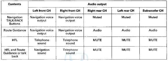
TJematics Muting Logic
The navigation system allows voice control for the audio, the XM, and the CD player. The navigation system uses the GA-Net bus to communicate the voice control commands to the audio unit When using the navigation TALK/BACK button, the audio is muted on all speakers and you hear navigation sound on the front channels. When using the navigation or route guidance (RG), the front speakers provides the navigation sound and the rear speakers continue to play the audio. For more information, see the navigation and HFL sections. The outline of the muting logic is shown in this table.
System Diagram
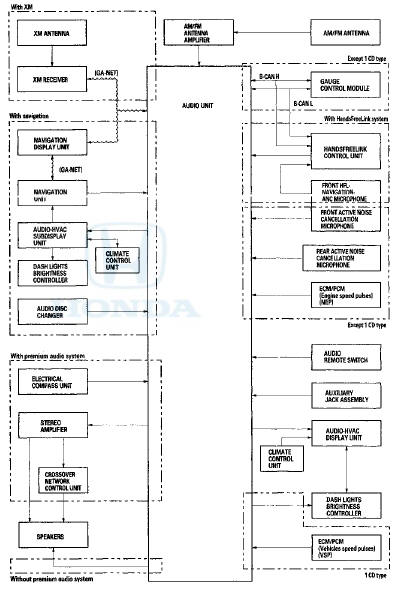
NOTE; All i t e m s m a y not a p p l y to t h i s v e h i c l e . S e e t h e o w n e r ' s m a n u a l f o r m o r e i n f o r m a t i o n.
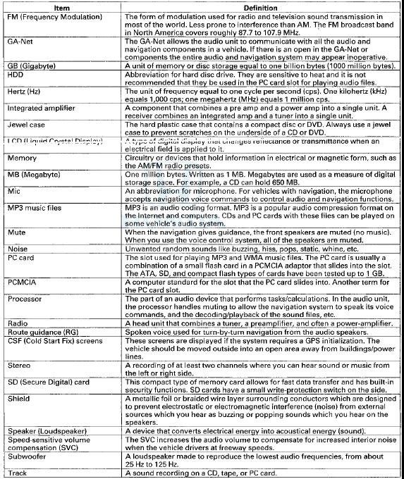
Audio Glossary
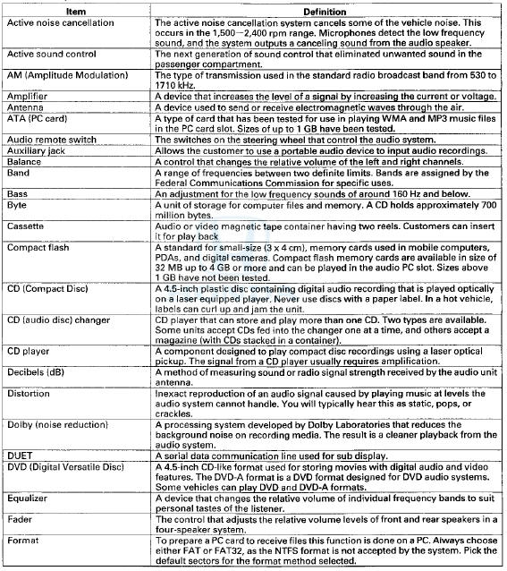
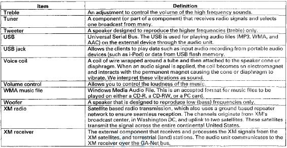
Audio Glossary (cont'd)
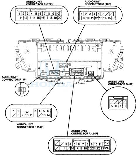
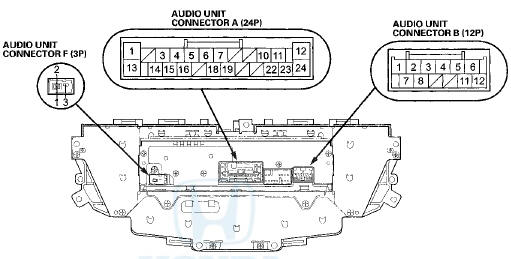
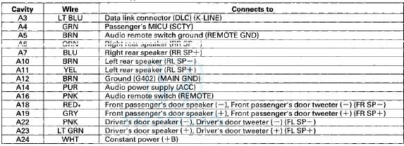
Audio Unit Connector for Inputs and Outputs
Premium Audio S f stem with navigation
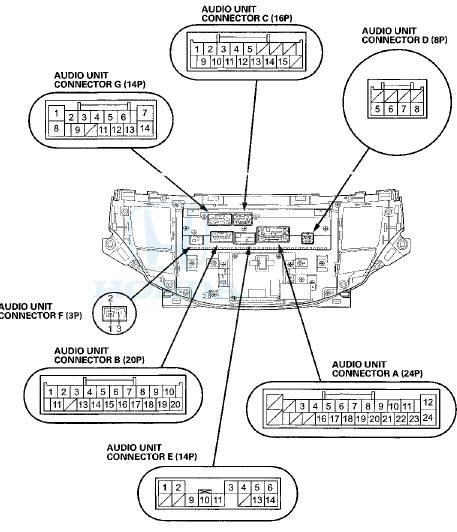
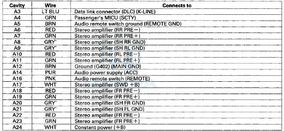
AUDIO UNIT CONNECTOR A (24P)
Terminal side of male terminals
Audio Unit Connector A (24P)
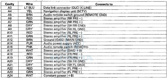
*The shielded wires have a heat-shrink tube insulating the outside of the wire. The color of the insulating tube, typically black or dark gray, may not match the color of the wire shown on the circuit diagram.
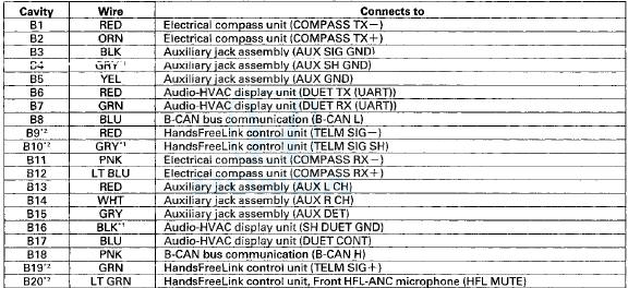
AUDIO UNIT CONNECTOR B (20P)
Terminal side of male terminals
Audio Unit Connector B (20P)
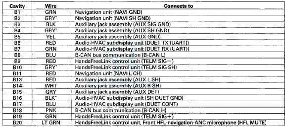
* The shielded wires have a heat-shrink tube insulating the outside of the wire. The color of the insulating tube, typically black or dark gray, may not match the color of the wire shown on the circuit diagram.
AUDIO UNIT CONNECTOR C (ISP)
Terminal side of male terminals
Audio Unit Connector C (ISP)
* The shielded wires have a heat-shrink tube insulating the outside of the wire. The color of the insulating tube, typically black or dark gray, may not match the color of the wire shown on the circuit diagram.
AUDIO UNIT CONNECTOR D (BP
)

Terminal side of male terminals
Audio Unit Connector D (8P)
* The shielded wires have a heat-shrink tube insulating the outside of the wire. The color of the insulating tube, typically black or dark gray, may not match the color of the wire shown on the circuit diagram.
AUDIO UNIT CONNECTOR E (14P)
Terminal side of male terminals
Audio Unit Connector E (14P)
* The shielded wires have a heat-shrink tube insulating the outside of the wire. The color of the insulating tube, typically black or dark gray, may not match the color of the wire shown on the circuit diagram.
AUDIO UNIT CONNECTOR F (3P)

Terminal side of male terminals
Audio Unit Connector F (3P)

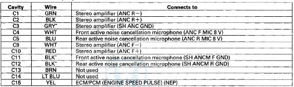
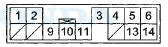
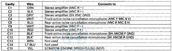
AUDIO UNIT CONNECTOR G (14P)
Terminal side of male terminals
Audio Unit Connector G (14P)
* The shielded wires have a heat-shrink tube insulating the outside of the wire. The color of the insulating tube, typically black or dark gray, may not match the color of the wire shown on the circuit diagram.
Audio Unit Connector for Inputs and Outputs
Premium Audio S f stem without Navigation
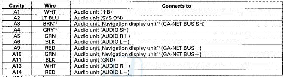
AUDIO UNIT CONNECTOR A (24P)
Terminal side of male terminals
Audio Unit Connector A (24P)
*The shielded wires have a heat-shrink tube insulating the outside of the wire. The color of the insulating tube, typically black or dark gray, may not match the color of the wire shown on the circuit diagram.
AUDIO UNIT C O N N E C T O R B (20P)
Terminal side of male terminals
Audio Unit Connector B (20P)
*1: The shielded wires have a heat-shrink tube insulating the outside of the wire. The color of the insulating tube, typically black or dark gray, may not match the color of the wire shown on the circuit diagram.
*2: With HandsFreeLink system
AUDIO UNIT CONNECTOR C (1SP)
Terminal side of male terminals
Audio Unit Connector C (ISP)
*The shielded wires have a heat-shrink tube insulating the outside of the wire. The color of the insulating tube, typically black or dark gray, may not match the color of the wire shown on the circuit diagram.
AUDIO UNIT CONNECTOR D (8P)

Terminal side of male terminals
Audio Unit Connector D (8P)
*The shielded wires have a heat-shrink tube insulating the outside of the wire. The color of the insulating tube, typically black or dark gray, may not match the color of the wire shown on the circuit diagram.
AUDIO UNIT CONNECTOR E (14P)
Terminal side of male terminals
Audio Unit Connector E (14P)
* The shielded wires have a heat-shrink tube insulating the outside of the wire. The color of the insulating tube, typically black or dark gray, may not match the color of the wire shown on the circuit diagram.
AUDIO UNIT CONNECTOR F (3P)

Terminal side of male terminals
Audio Unit Connector F (3P)
Audio Unit Connector for Inputs and Outputs
Without Premium Audio System
1 CD type

AUDIO UNIT CONNECTOR A (24P) (1 CD Type)
Terminal side of male terminals
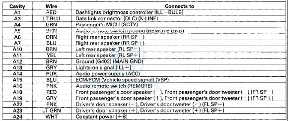
Audio Unit Connector A (24P) (1 CD Type)
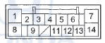
AUDIO UNIT CONNECTOR B (12P) (1 CD Type)
Terminal side of male terminals
Audio Unit Connector B (12P) (1 CD Type)
*The shielded wires have a heat-shrink tube insulating the outside of the wire. The color of the insulating tube, typically black or dark gray, may not match the color of the wire shown on the circuit diagram.
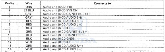
AUDIO UNIT CONNECTOR A (24P) (6 CD Type)
Terminal side of male terminals
Audio Unit Connector A (24P) (S CD Type)
AUDIO UNIT CONNECTOR B (20P) (6 CD Type)

Terminal side of male terminals
Audio Unit Connector B (20P) (6 CD Type)
*The shielded wires have a heat-shrink tube insulating the outside of the wire. The color of the insulating tube, typically black or dark gray, may not match the color of the wire shown on the circuit diagram.
AUDIO UNIT CONNECTOR C (16P) (S CD Type)
Terminal side of male terminals
Audio Unit Connector C (16P) (6 CD Type)
* The shielded wires have a heat-shrink tube insulating the outside of the wire. The color of the insulating tube, typically black or dark gray, may not match the color of the wire shown on the circuit diagram.
AUDIO UNIT CONNECTOR F (3P)

Terminal side of male terminals
Audio Unit Connector F (3P)
Stereo Amplifier Connector for Inputs and Outputs (With Premium Audio System)
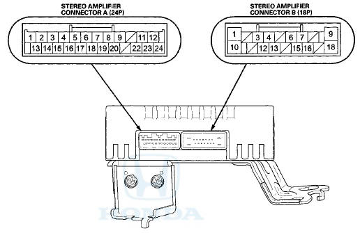
STEREO AMPLIFIER CONNECTOR A (24P)
Terminal side of male terminals
Stereo Amplifier Connector A (24P)
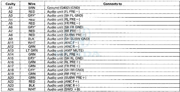
*The shielded wires have a heat-shrink tube insulating the outside of the wire. The color of the insulating tube, typically black or dark gray, may not match the color of the wire shown on the circuit diagram.
STEREO AMPLIFIER CONNECTOR B (18P)
Terminal side of male terminals
Stereo Amplifier Connector B (1SP)
XM Receiver Connector for Inputs and Outputs (With Premium Audio S f stem)
4-Door

2-Door
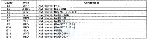
KM RECEIVER CONNECTOR A (14PJ
Terminal side of male terminals
XM Receiver Connector A (14P)
*1: With navigation
*2: The shielded wires have a heat-shrink tube insulating the outside of the wire. The color of the insulating t u b e , typically black or dark gray, may not match the color of the wire shown on the circuit diagram.
XM RECEIVER CONNECTOR B (2P)

Terminal side of male terminals
XM Receiver Connector B (2P)

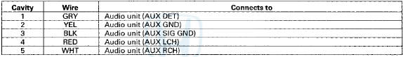
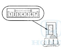
Auxiliary Jack Assembly Connector for Inputs and Outputs
Auxiliary J a c k Assembly 5P Connector
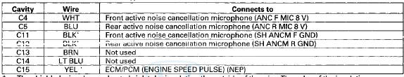
Active Noise Cancellation Microphone Connector for inputs and Outputs
Front HFL-Navigation-ANC Microphone (With Navigation)
Front Active Noise Cancellation Microphone (Without Navigation 6 CD Type)
Rear Active Noise Cancellation Microphone

Front HFL-navlgation-ANC Microphone 7P Connector (with navigation)

Front Active Noise Cancellation Microphone 3P Connector (without navigation В§ CD type)

* The shielded wires have a heat-shrink tube insulating the outside of the wire. The color of the insulating tube, typically black or dark gray, may not match the color of the wire shown on the circuit diagram.
Rear Active Noise Cancellation Microphone 3P Connector

* The shielded wires have a heat-shrink tube insulating the outside of the wire. The color of the insulating tube, typically black or dark gray, may not match the color of the wire shown on the circuit diagram.
Audio Disc Changer Connector for Inputs and Outputs (With Navigation)
Audio Disc Changer 14P Connector
*: The shielded wires have a heat-shrink tube insulating the outside of the wire. The color of the insulating tube, typically black or dark gray, may not match the color of the wire shown on the circuit diagram.
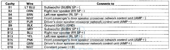
Speaker Crossover Wetwork Control Unit Connector for Inputs and Outputs (With Premium Audio System)

D r i v e r ' s Door Speaker Crossover Network Control Unit 8P Connector
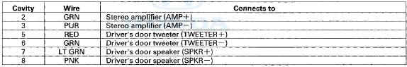
Front Passenger's Door Speaker Crossover Network Control Unit 8P Connector
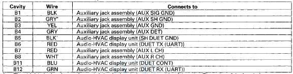
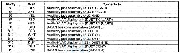
Audio-HVAC Subdisplay Unit Connector for inputs and Outputs (With Navigation)
Audio-HVAC Subdisplay Unit 12P Connector
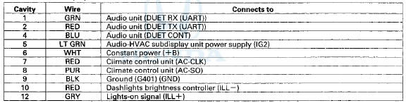
Audio-HVAC Display Unit Connector for Inputs and Outputs (Without Navigation)
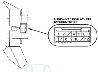
Audio-HVAC Display Unit 12P Connector
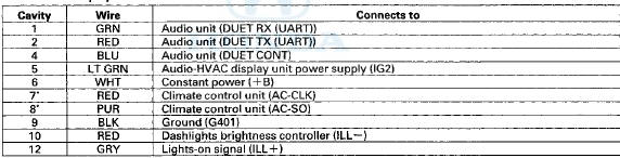
* With climate control

 Circuit Diagram
Premium Audio System with navigation
Premium Audio System with navigation
Premium Audio System without navigation
Premium Audio System without navigation
Without Premium Audio Syst ...
See also:
Middle Floor Undercover
Replacement
Left Side
NOTE:
- Put on gloves to protect your hands.
- Take care not to scratch the body.
1. Remove the bolts and release the hook (A), then
remove the left middle floor undercover (B).
...
Transmission Range Switch Test
1. Raise the vehicle on a lift, or apply the parking brake,
block the rear wheels, and raise the front of the
. vehicle. Make sure it is securely supported.
2. Remove the left front wheel.
3. ...
A/C Compressor Replacement
NOTE: Do not install the A/C compressor into a system
unless you are completely sure that the system is free of
contamination. Installing the A/C compressor into a
contaminated system can result in ...