 Honda Accord: System Description
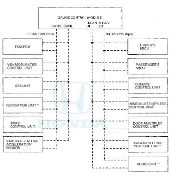
Body Controller Area Network (B-CAN) and Fast Controller Area Network (F-CAN)
The body controller area network (B-CAN) and the fast controller area network (F-CAN) share information between multiple electronic control units (ECUs). B-CAN communication moves at a slower speed (125 kbps) for convenience related items and for other functions. F-CAN information moves at a faster speed (500 kbps) for "real time" functions such as fuel and emissions data. To allow both systems to share information, the gauge control module translates and relays the information from B-CAN to F-CAN and from F-CAN to B-CAN. This is called the Gateway Function.
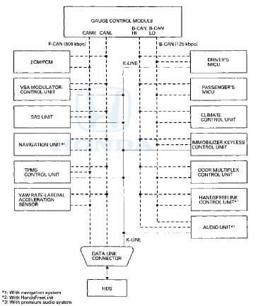
*1: With navigation system
*2: With HandsFreeLink
*3; With premium audio system
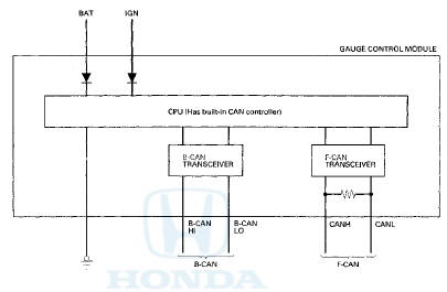
Gateway Function
The gauge control module acts as a gateway to allow both systems to share information. The gauge control module translates and relays the information from B-CAN to F-CAN and from F-CAN to B-CAN.
Network "Loss of Communication" Error Checking Function
The ECUs on the CAN circuit send messages to each other. If there are any communication malfunctions on the network, the LCD display on the gauge control module can indicate the error messages by entering the gauge control module self-diagnostic function (see page 22-332).
Self-diagnostic Function (On-board diagnosis)
By connecting the HDS to the data link connector (DLC), the HDS can retrieve the diagnostic information from the driver's MICU via a diagnostic line called the K-LINE. The K-LINE is a separate communication line from the CAN lines, and is connected to most of the CAN related ECUs. The driver's MICU is a gateway between the HDS and B-CAN related ECUs, and sends B-CAN diagnostic information to the HDS. When doing a function test with the HDS, the HDS sends an output signal through the K-LINE to the driver's MICU. The driver's MICU either relays the request to another ECU, or commands the function itself.
Wake-up and Sleep Function
The multiplex integrated control system has "wake-up" and "sleep" functions to decrease parasitic draw on the battery when the ignition switch is in LOCK (0).
• In the sleep mode, the multiplex integrated control system stops functioning (communication and CPU control) when it is not necessary for the system to operate.
• As soon as any operation is requested (for example, a door is unlocked), the related control units in the sleep mode immediately wake up and begin to function.
• When the ignition switch is turned to LOCK (0), and the driver's door is opened, then closed, there is a delay of about 40 seconds before the control unit goes from the wake-up mode to the sleep mode.
• The sleep mode will not function if any door or the trunk lid is open, or if a key is in the ignition switch.
NOTE: Sleep and Wake-up Mode Test (see page 22-140).
Fail-safe Function
To prevent improper operation, the MICU has a fail-safe function. In the fail-safe mode, the output signal is fixed when any part of the system malfunctions (for example, a faulty control unit or communication line).
Each control unit has a hardware fail-safe function that fixes the output signal when there is a CPU malfunction, and a software fail-safe function that ignores the signal from a malfunctioning control unit, which allows the system to operate normally.
Hardware Faii-safe Control
Fail-safe function
When a CPU problem or a abnormal power supply voltage is detected, the MICUs move to the hardware fail-safe mode, and each system output load is set to the pre-programmed fail-safe value.
Software Fail-safe Control
When data from the B-CAN circuit cannot be received within a specified time, or if an unusual combination of data is recognized, the MICU switches to its fail-safe mode, which uses a pre-programmed value.
Driver's MICU
Power Supply Voltage Monitoring Function
The driver's MICU monitors the power supply voltage (back-up voltage). If the voltage goes below 10 V, the driver's MICU will not store a DTC.

Entry Lights Control System (Ceiling Lights, Map Lights, Ignition Key Light)*
The driver's MICU control of the ceiling light ON/OFF is based on input signals from each switch.
*: The security system can be customized in the odo/trip display to suit the customer's needs. For more information about keyless/security system options, refer to the Owner's Manual.
Collision Detection Signal (CDS)
The driver's MICU control of the door lock actuators is based on IG1 and SRS (CDS) inputs.

Key Interlock (A/T)
The driver's MICU control of the key interlock solenoid is based on ignition switch ACCESSORY (I) position, the transmission range switch P position, and the park-pin switch inputs.

Rear Window Defogger Timer Operation (With Climate Control)
The driver's MICU control of the rear window defogger timer is based on ignition switch and rear window defogger switch inputs.

Rear Window Defogger Timer Operation (With HVAC Control)
The driver's MICU control of the rear window defogger timer is based on the ignition switch and rear window defogger switch inputs.
A/C Pressure Sensor
The driver's MICU sends A/C pressure sensor signal information when the ignition switch is in the IG1 position.

Combination Light Switch
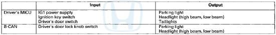
The driver's MICU control of the lighting system is based on inputs from each combination light switch.
Daytime Running Lights
The driver's MICU control of the headlights as daytime running lights is based on inputs from each switch.
Hleadlight Auto-OFF Function
The driver's MICU control of the lighting system is based on inputs from each switch.
Turn Signal/Hazard Warning Lights
The driver's MICU control of the turn signal/hazard warning lights is based on inputs from the turn signal switch and the hazard warning switch.
Courtesy Light (Driver's side)
The driver's MICU control of the driver's and left rear door courtesy lights is based on inputs from the driver's and left rear door switches.

Wiper
The driver's MICU control of the wiper is based on inputs from each switch.
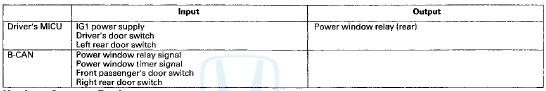
Power window relay
The driver's MICU control of the power windows is based on inputs from each switch.
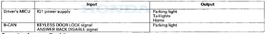
Keyless Answer Back
The driver's MICU control of the lighting system and horns is based on keyless data sent by B-CAN.
Security Answer Back*
The driver's MICU control of the lighting system and horns is based on keyless data sent by B-CAN.
*: The security system can be customized in the odo/trip display to suit the customer's needs. For more information about keyless/security system options, refer to the Owner's Manual.
Answer Back Response Operation*
The driver's MICU control of the lighting system and horns is based on keyless data sent by B-CAN.
*: The security system can be customized in the odo/trip display to suit the customer's needs. For more information about keyless/security system options, refer to the Owner's Manual.
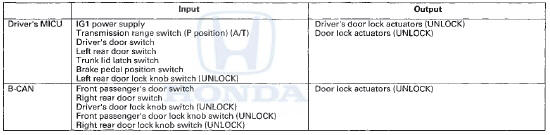
Power Door Locks*
The driver's MICU control of the door lock actuators is based on inputs from each switch.
*: The security system can be customized in the odo/trip display to suit the customer's needs. For more information about keyless/security system options, refer to the Owner's Manual.
Door Lock Response Operation*
The driver's MICU control of the door lock actuators LOCK, UNLOCK, DRIVER'S UNLOCK, TRUNK UNLOCK is based on B-CAN door lock switch signals.
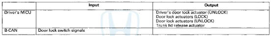
*: The security system can be customized in the odo/trip display to suit the customer's needs. For more information about keyless/security system options, refer to the Owner's Manual.
Keyless Entry System*
The driver's MICU control of the door lock actuators is based on inputs from each switch.
*: The security system can be customized in the odo/trip display to suit the customer's needs. For more information about keyless/security system options, refer to the Owner's Manual.
Keyless PANIC Function
The driver's MICU control of the keyless PANIC function is based on B-CAN data.
Auto Power Door Locks (LOCK operation)*
The driver's MICU control of the door lock actuators is based on inputs from each switch.
*: The security system can be customized in the odo/trip display to suit the customer's needs. For more information about keyless/security system options, refer to the Owner's Manual.
Auto Power Door Locks (UNLOCK operation)*
The driver's MICU control of the door lock actuators is based on inputs from each switch.
*: The security system can be customized in the odo/trip display to suit the customer's needs. For more information about keyless/security system options, refer to the Owner's Manual.
Security Alarm System*
The driver's MICU control of the lighting system and horns is based on inputs from each switch and B-CAN data.
*: The security system can be customized in the odo/trip display to suit the customer's needs. For more information about keyless/security system options, refer to the Owner's Manual.
Passenger's MICU
Power Supply Voltage Monitoring Function
The passenger's MICU monitors the power supply voltage (back-up voltage), If the voltage goes below 10 V, the passenger's MICU will not store DTCs.

Courtesy Light (Front passenger's side)
The passenger's MICU control of the front passenger door courtesy light is based on inputs from the front passenger door switch.

Power Door Locks (LOCK)*
The passenger's MICU control of the front passenger's side door lock actuators is based on inputs from the driver's MICU.

*: The security system can be customized in the odo/trip display to suit the customer's needs. For more information about keyless/security system options, refer to the Owner's Manual.
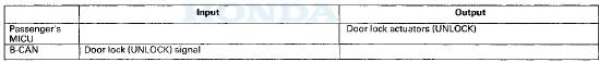
Power Door Locks (UNLOCK)*
The passenger's MICU control of the front passenger's side door lock actuators is based on inputs from the driver's MICU.
*: The security system can be customized in the odo/trip display to suit the customer's needs. For more information about keyless/security system options, refer to the Owner's Manual.
Exterior Lights*
The passenger's MICU control of the front passenger's side headlight, and parking lights is based on inputs from the driver's MICU.
*: The security system can be customized in the odo/trip display to suit the customer's needs. For more information about keyless/security system options, refer to the Owner's Manual.
Automatic Lighting
The passenger's MICU control of the headlights and the parking lights is based on inputs from the automatic lighting sensor.
Washer Operation
The passenger's MICU control of the washer motor is based on inputs from the wiper switch.

Power Window Relay Circuit
The passenger's MICU control of the power window relay circuit in the passenger's under-dash fuse/relay box is based on inputs from the power window switches.
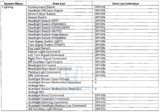
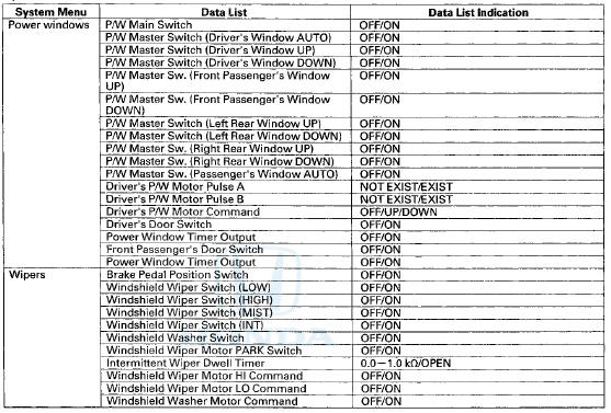
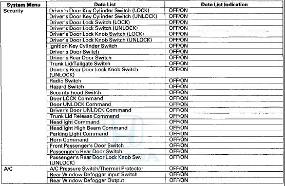
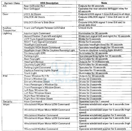
HDS Inputs and Commands
Certain Inputs happen so quickly that the HDS cannot update fast enough. Hold the switch that is being tested while monitoring the Data List. This should give the HDS time to update the signal on the Data List.
Because the HDS software is updated to support the release of newer vehicles it is not uncommon to see system function tests that are not supported.
Make sure that the most current software is loaded.
Input:
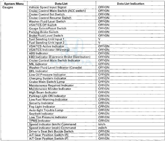
HDS Inputs and Commands
Input;
Input: (cont'd)
Input: (cont'd)
Functor Test:
 DTC Troubleshooting Index
NOTE: Record all DTCs, and sort them by DTC type using the DTC
troubleshooting index, then troubleshoot the DTC(s)
in this order:
• Battery voltage DTCs
• Internal error DTCs
• Lo ...
 Troubleshooting
B-CAN System Diagnosis Test Mode
A
Troubleshooting
B-CAN System Diagnosis Test Mode
A
Check the ECM/PCM for DTCs and troubleshoot .
ECM/PCM (see page 11-3) or F-CAN loss of
communication errors first, then do this diagnosis if the
symptom is related to the B-CAN system.
1. Comp ...
See also:
ODS Unit Operation Check
Check the ODS operation after any of these actions:
• Replacement of front passenger's seat component(s)
(except ODS unit and/or weight sensors)
• After a vehicle collision
• SRS un ...
Speaker Test/Replacement
Front Door Speaker
1. Remove the door panel.
• 4-door (see page 20-17)
• 2-door (see page 20-12)
2. Remove t h e bolt (A). Then lift the speaker straight up
to release t h e lower cli ...
Compatible iPod®, iPhone®, and USB Flash Drives
• iPod® and iPhone® Model Compatibility
This system may not work with all software versions
of these devices.
• USB Flash Drives
• Use a recommended USB flash drive of 256 MB or higher. ...