 Honda Accord: Symptom Troubleshooting
VSA activation indicator does not go off, and no DTCs are stored
NOTE: If the VSA modulator was replaced prior to the activation indicator turning on, do the VSA sensor neutral position memorization (see page 19-133).
1. Turn the ignition switch to ON (II).
2. Check the VSA activation indicator for several seconds when the ignition switch is turned to ON (II).
Does the indicator come on then go off? YES-The system is OK at this time.
NO-Go to step 3.
3. Turn the ignition switch to LOCK (0).
4. Disconnect the VSA OFF switch 5P connector (see page 19-134).
5. Check the VSA OFF switch (see page 19-134).
Is the VSA OFF switch OK? YES-Go to step 6.
NO-Replace the VSA OFF switch (see page 19-134).
6. Disconnect the gauge control module 32P connector (see page 22-351).
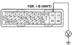
7. Check for continuity between VSA OFF switch 5P connectorterminal No. 2 and body ground.
VSA OFF SWITCH 5P CONNECTOR
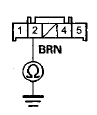
Wire side of female terminals
Is there continuity? YES
-Repair a short to body ground in the wire between the gauge control module and the VSA OFF switch.
NO
-Substitute a known-good gauge control module (see page 22-351), then go to step 1 and recheck. If it is OK, replace the original gauge control module (see page 22-351 ).
ABS indicator, brake system indicator, and VSA indicator do not go off
1. Turn the ignition switch to LOCK (0).
2. Check the No. 6 (7.5 A) fuse in the driver's under-dash fuse/relay box.
Is the fuse blown? YES
-Go to step 3.
NO
-Reinstall the checked fuse, then go to step 9.
3. Disconnect the VSA modulator-control unit 36P connector (see step 3 on page 19-137).
4. Disconnect the yaw rate-lateral acceleration sensor 5P connector (see page 19-133).
5. Check for continuity between VSA modulator-control unit 36P connector terminal No. 30 and body ground.
VSA MODULATOR-CONTROL UNIT 36P CONNECTOR
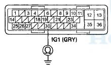
Wire side of female terminals
Is there continuity? YES
-Repair a short to body ground in the wire between the No. 6 (7.5 A) fuse in the driver's under-dash fuse/relay box and the VSA modulatorcontrol unit or the yaw rate-lateral acceleration sensor.
NO
-lnstall a new No. 6 (7.5 A) fuse in the driver's under-dash fuse/relay box, then go to step 6.
6. Reconnect all connectors.
7. Turn the ignition switch to ON (II).
8. Check the ABS indicator, the brake system indicator and the VSA indicator for several seconds when the ignition switch is turned to ON (II).
Do the indicators come on then go off? YES-
The troubleshooting is complete.
NO
-Replace the VSA modulator-control unit (see page 19-136).
9. Do the gauge control module troubleshooting (see page 22-332).
Is the gauge control module OK? YES
-Go to step 10.
NO
-Substitute a known good gauge control module (see page 22-351). If it is OK, replace the original gauge control module (see page 22-351).
10. Disconnect the VSA modulator-control unit 36P connector (see step 3 on page 19-137).
11. Turn the ignition switch to ON (II).
12. Measure the voltage between VSA modulator-control unit 36P connector terminal No. 30 and body ground.
VSA MODULATOR-CONTROL UNIT 36P CONNECTOR
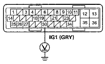
Wire side of female terminals
Is there battery voltage? YES
-Go to step 13.
NO
-Repair an open in the wire between the No. 6 (7.5 A) fuse in the driver's under-dash fuse/relay box and the VSA modulator-control unit.
13. Turn the ignition switch to LOCK (0).
14. Check for continuity between VSA modulator-control unit 36P connector terminal No. 35 and body ground.
VSA MODULATOR-CONTROL UNIT 36P CONNECTOR
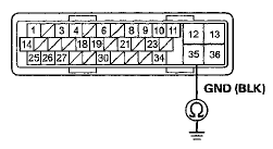
Wire side of female terminals
Is there continuity? YES
-Go to step 15.
NO
-Repair an open in the wire between the VSA modulator-control unit and body ground (G202).
15. Measure the voltage between VSA modulator-control unit 36P connector terminal No. 12 and body ground.
VSA MODULATOR-CONTROL UNIT 36P CONNECTOR
Wire side of female terminals
Is there battery voltage? YES
-Go to step 16.
NO
-Repair an open in the wire between the No. 2 (40 A) fuse in the under-hood fuse/relay box and the VSA modulator-control unit.
16, Disconnect the gauge control module 32P connector (see page 22-351).
17. Check for continuity between the VSA modulatorcontrol unit 36P connector terminal and gauge control module 32P connector terminal (see table).
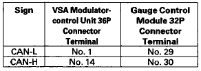
VSA MODULATOR-CONTROL UNIT 36P CONNECTOR
Wire side of female terminals
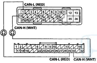
GAUGE CONTROL MODULE 32P CONNECTOR
Wire side of female terminals
I s there continuity? YES
-Go to step 18.
NO
-Repair an open in the wire between the gauge control module and the VSA modulator-control unit.
18. Reconnect all connectors.
19. Update the VSA modulator-control unit if it does not have the latest software (see page 19-135). If the unit already has the latest software, substitute a knowngood VSA modulator-control unit (see page 19-136).
20. Turn the ignition switch to LOCK (0), then turn it to ON (II) again.
21. Check the ABS indicator, the brake system indicator and the VSA indicator for several seconds when the ignition switch is turned to ON (II).
Does the indicators come on then go off? YES
-lf the VSA modulator-control unit was updated, troubleshooting is complete. If the VSA modulatorcontrol unit was substituted, replace the original VSA modulator-control unit (see page 19-136).
NO
-Check for loose terminals in the VSA modulatorcontrol unit 36P connector. If the VSA modulatorcontrol unit was updated, substitute a known-good VSA modulator-control unit (see page 19-136), then retest. If the VSA modulator-control unit was substituted, go to step 1.
 DTC Troubleshooting
DTC 11-13: Right-front Wheel Speed Sensor
Circuit Malfunction
DTC 13-13; Left-front Wheel Speed Sensor
Circuit Malfunction
DTC 15-13: Right-rear Wheel Speed Sensor
Circuit Malfunction
DTC 17-13: ...
 Steering Angle Sensor Replacement
SRS components are located In this area. Review the SRS component locations:
4-door (see page 24-21), 2-door (see
page 24-23) and the precautions and procedures (see page 24-25).
NOTE: Do not da ...
See also:
Cam Chain Removal
NOTE: Keep the cam chain away from magnetic fields.
1. Remove the front wheels.
2. Remove the splash shield (see step 25 on page 5-5).
3. Remove the drive belt (see page 4-30).
4. Remove t ...
Regulator Valve Body Disassembly,
Inspection, and Reassembly
1. Clean all parts thoroughly in solvent and dry them with compressed air.
Blow out all passages.
2. Inspect the valve body for scoring and damage.
3. Check all valves for free movement. If an ...
Adjust the Front Seats.
Adjust the driver’s seat as far to the
rear as possible while allowing you to
maintain full control of the vehicle.
Have a front passenger adjust their
seat as far to the rear as possible.
...