 Honda Accord: Steering Gearbox Installation
Special Tools Required
-Subframe Adapter VSB02C000016*
-Subframe Alignment Pin 070AG-SJAA10S
-Engine Support Hanger, A and Reds AAR-T1256*
-Engine Hanger Adapter VSB02C000015*
*: Available through the Honda Tool and Equipment Program, 888-424-6857.
SRS component locations: 4-door (see page 24-21), 2-door (see page 24-23) and the precautions and procedures (see page 24-25) before doing repairs or service.
1. Before installing the steering gearbox, make sure that no power steering fluid is on the mating surface of the steering gearbox and the front subframe. To prevent the gearbox mounting bolts from loosening after the installation, remove any power steering fluid from the mount cushions and the bolt holes.
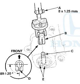
2. Wrap vinyl tape over the splines on the pinion shaft (A).
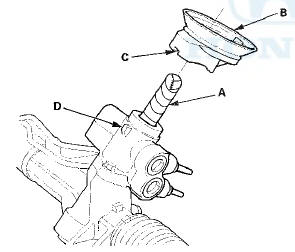
3. Install the pinion shaft grommet (B). Align the slot ,(C) in the pinion shaft grommet with the lug portion (D) on the valve housing. Make sure there is no gap between the grommet and the valve housing.
4. Turn the lip (A) of the pinion shaft grommet.
5. Slide the steering gearbox (B) between the front subframe and the body from the driver's side.
6. Carefully move the steering gearbox (A) toward the passenger's side until the pinion shaft clears the fenderwell opening on the body.
7. Continue moving the gearbox toward the passenger's side until the steering gearbox is in position.
8. Install the washers (A), the stiffener plates (B), the new mounting bolts (C), and the flange bolts (D) on the driver's side of the gearbox. Then loosely install the mounting bolts and the flange bolts.
9. Position the cutout (A) on the mounting cushion (B) as shown, and install it on the passenger's side of the steering gearbox.
10. Install the gearbox mounting bracket (C) over the mounting cushion, and tighten the flange bolts (D) to the specified torque.
11. Tighten the flange bolts on the driver's side of the steering gearbox to the specified torque alternately in two steps.
12. Install the front subframe front stiffeners (A) and the front subframe rear stiffeners (B), then loosely install the new front subframe mounting bolts (C), the new flange bolts (D), and the flange bolts (E).
13. Align the front subframe using the 15.7 mm end of the subframe alignment pin. Vertically install the subframe alignment pin, and align the right rear corner of the front subframe and the vehicle frame holes, then loosely tighten the subframe mounting bolt (A) until the front subframe contacts the body frame.
14. Loosely tighten the left rear subframe mounting bolt with the same procedure as the right rear using the subframe alignment pin.
15. Tighten the right rear subframe mounting bolt (A) to the specified torque with the subframe alignment pin installed.
16. Tighten the left rear subframe mounting bolt to the specified torque with the subframe alignment pin installed.
17. Tighten the subframe mounting bolts (A) to the specified torque.
18. Tighten the flange bolts (B) to the specified torque.
19. Tighten the flange bolts (A) to the specified torque.
20. Install the flange nuts (A) to the lower transmission mount, and tighten them to the specified torque.
21. Install the new front subframe middle mounting bolts
on the driver's side, and tighten them to the specified
torque.
22. Install the new front subframe middle mounting bolts on the passenger's side, and tighten them to the specified torque.
23. Lower the transmission jack supporting the front subframe.
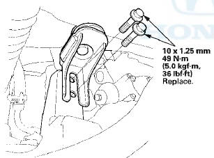
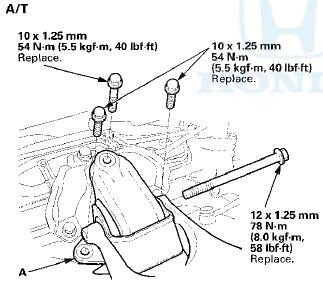
24. A/T: Install the rear engine mount upper bracket (A) to
the base bracket (B) with a new mounting bolt (C) and
mounting bolts (D), and tighten them to the specified torque.
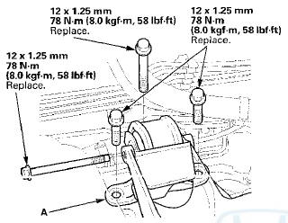
25. Install the rear engine mount (A) with new mounting bolts, and lightly tighten them.
M/T
26. Remove the engine support hanger, the hanger balance bar, and the hanger adapter set.
27. Tighten the rear engine mount mounting bolts to the specified torque.
28. install the new damper fork mounting bolt (A) and the new mounting nut (B), and loosely tighten the nut.
29. Install exhaust pipe A (see page 9-9).
30. Install the front splash shield (see page 20-291).
31. Lower the vehicle.
32. On both sides, wipe off any grease contamination from the ball joint tapered section and threads.
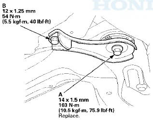
Reconnect the tie-rod end ball joint (A) to the knuckle.
Install the nut (B), and tighten it to the specified torque.
33. Install a new cotter pin (C), and bend it as shown.
34. Loosely connect the return line and inlet line to the valve housing by hand.
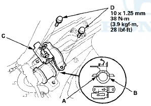
35. Install the return line clamp bolt (A), and tighten it to the specified torque.
36. Install the return line (B) to the return hose clamp (C), and clamp it.
37. Install the inlet line clamp bracket bolt (A) and the return hose clamp bracket bolt (B), and tighten them to the specified torque.
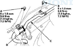
38. Install the return hose (C) to the return hose clamp (D), and clamp it.
39. Install the inlet line clamp bracket bolt (A) and the return line clamp bolt (B), and tighten them to the specified torque.
40. Tighten the flare nuts to the specified torque.
41. Install the P/S heat shield (A) with the flange bolts, and tighten them to the specified torque.
42. Install the strut brace (see page 20-306).
43. Install the front grille cover:
-4-door (see page 20-274)
-2-door (see page 20-274)
44. Place a floor jack under the lower arm, and raise the suspension to load it with the vehicle's weight.Do not place the jack against the ball joint pin of the knuckle.
45. Tighten the damper fork mounting nut while holding the mounting bold to the specified torque (see step 28).
46. Install the front wheels, then set the wheels in the straight ahead position.
NOTE: Before installing the wheel, clean the mating ' surfaces of the brake disc and the inside of the wheel.
47. Center the steering rack within its stroke.
48. Loosen the upper steering joint bolt (A), and slip the lower end of the steering joint (B) onto the pinion shaft (C) taking care to align the gap (D) within the angle.
NOTE: Pick up the tabs (E) of the pinion shaft grommet, and turn up the lip of the pinion shaft grommet securely in place. Make sure that light does not enter from the space between the pinion shaft grommet and the body.
49. Align the bolt hole (A) on the steering joint with the groove (B) around the pinion shaft, then loosely install the lower steering joint bolt (C). Be sure that the joint bolt is securely in the groove in the pinion shaft.
50. Pull on the steering joint to make sure that the steering joint is fully seated, then tighten the lower joint bolt to the specified torque.
51. Tighten the upper steering joint bolt (D) to the specified torque, 52. Install the steering joint cover (A).
53. Install the steering wheel (see page 17-9), and the driver's airbag (see page 24-211).
54. Do the battery terminal reconnection procedure (see page 22-91), and check these items: -Turn the ignition switch to ON (II) and check that the SRS indicator comes on for about 6 seconds, and then goes off.
-Make sure the horn and turn signal switches work properly.
-Make sure the steering wheel switches work properly.
55. Fill the system with power steering fluid, and bleed air from the system (see page 17-28).
56. After installation, check these items.
-Start the engine, allow it to idle, and turn the steering wheel from lock to lock several times to warm up the fluid. Check the gearbox for leaks (see page 17-27).
-Check the steering wheel spoke angle.
-If steering spoke angles to the right and left are not equal (steering wheel and rack are not centered), correct the engagement of the joint/pinion shaft serrations.
-Set the steering column to the center tilt position, and to the center telescopic position, then do the front toe inspection (see page 18-5).
 Steering Gearbox Overhaul
Exploded View
Special Tools Required
-Cylinder End Seal Remover Attachment
07TAF-SZ50100
-Valve Seal Ring Sizing Tool 07NAG-SR3090A
-Sleeve Seal Guide, 35.9 x 37
07YAG-S2X0100
-Sizing Tool, ...
 Suspension
...
See also:
Security System
The security system helps to protect
your vehicle and valuables from theft.
The horn sounds and a combination
of headlights, parking lights, side
marker lights and taillights flashes if
someo ...
Control Arm Replacement
1. Raise and support the vehicle {see page 1-13).
2. Remove the rear wheel.
3. Remove the control arm mounting self-locking nut (A)
and the washer (B) from the knuckle side.
NOTE; Use a new ...
Advice for Pregnant Women
If you are pregnant, the best way to
protect yourself and your unborn
child when driving or riding in a
vehicle is to always wear a seat belt,
and keep the lap part of the belt as
low as p ...