 Honda Accord: Steering Column Inspection
Inspection
1. Remove the steering column (see page 17-10).
2. Check these items; •Check for loose bearing mounting nuts (A). If they are loose, replace the column as an assembly.
-Check the steering column ball bearings (B) and the steering joints (C) for play and proper movement. If any bearing is noisy or has excessive play, replace the steering column as an assembly.
-Check the sliding capsules (D) for distortion or breakage. If there is distortion or breakage, replace the steering column as an assembly.
-Check the tilt mechanism and telescopic mechanism for movement and damage.
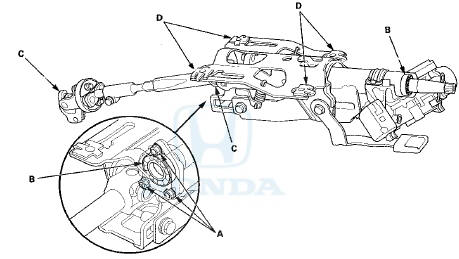
3. Install the steering column (see page 17-12).
Check of Tilting Force
1. Set the steering wheel in the straight ahead driving position, and loosen the lock lever fully.
2. Attach a commercially available spring scale (A) to the highest point of the steering wheel, and tilt the steering column to the lowest position.
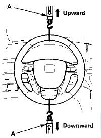
3. Pull the spring scale straight up, and read the force required to move the steering column.
4. Attach the spring scale to the lowest point of the steering wheel.
5. Pull the spring scale straight down, and read the force required to move the steering column.
Tilting force (upward/downward): Standard: 70 N (7.1 kgf, 15 Ibf) max.
6. If the measurement is higher than specified, or if the tilt function feels rough, do the following.
-Loosen the attaching nuts so they are finger-tight.
-Release the lock lever, and tilt and telescope the steering column several times.
-Tilt the column down, then tighten the lock lever.
-Torque the upper nuts, then torque the lower bolts.
7. Test the tilting force again. If the force is still higher than the specification, replace the steering column as an assembly (see page 17-10).
Check of Telescoping Force
1. Set the steering wheel in the straight ahead driving position, and loosen the lock lever fully, and push in the steering wheel to the fully telescoped in position.
2. Attach a commercially available spring scale (A) to the center point of the steering wheel as shown.
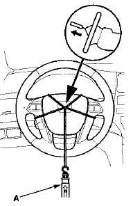
3. Pull the spring scale, and read the force required to move the steering column during telescoping out.
Telescoping force: Standard: 135 N (13.8 kgf, 30.3 Ibf) max.
4. If the measurement is higher than specified, replace the steering column as an assembly (see page 17-10).
Check of Lock Lever force
1. Move the lock lever (A) from the loosened position to the locked position three to five times, then release the lock lever. Adjust the steering column to the center tilt position and also to the full telescopic out position, and hold the steering wheel.
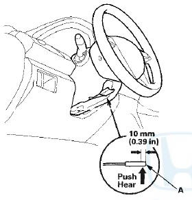
2. Using a commercially available push-pull gauge, push up the lock lever 10 m m (0.39 in) in from its end, and measure the force required to move the lock lever.
Lock lever force: 50—85 N (5.1 ~8.7 kgf, 11 - 1 9 Ibf) min
3. If the measurement is higher than specified, replace the steering column as an assembly (see page 17-10).
 Steering Column Removal and Installation
SRS components are located in this area. Review the
SRS component locations: 4-door (see page 24-21 )f
2-door (see page 24-23) and the precautions and
procedures (see page 24-25) before doing repai ...
 Steering Lock Replacement
1. Remove the steering column (see page 17-10).
2. Center-punch both of the two shear bolts, and drill
their heads off with a 5 mm (0.20 in) drill bit. Be careful
not to damage the steering lock ...
See also:
Rocker Arm Oil Pressure Switch A
Removal/Installation
PZEV model
1. Remove the rocker arm oil control valve (see page
11-275).
2. Remove rocker arm oil pressure switch A.
3. Install the parts in the reverse order of removal with a
new O-ring (B) ...
Using Automatic Climate Control
The automatic climate control system maintains the interior temperature you
select.
The system also selects the proper mix of heated or cooled air that will as
quickly as
possible, raise or l ...