 Honda Accord: Relays
Power Relay Test
Special Tools Required
Relay Puller 07AAC-000A1A0
Use this chart to identify the type of relay, then do the test listed for it.
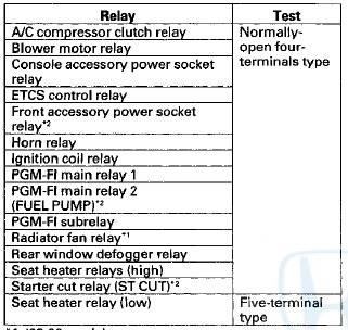
*1:'08-09 models
*2: Carefully remove the relay from the driver's under-dash fuse/relay box using the relay puller. Do not use pliers. Pliers will damage the relay.
Normally-open Four-terminal Type
Check for continuity between the terminals: • There should be continuity between terminals No. 1 and No. 2 when battery power is connected to terminal No. 4, and body ground is connected to terminal No. 3.
• There should be no continuity between terminals No. 1 and No. 2 when power is disconnected.
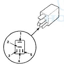
Five-terminal Type
Check for continuity between the terminals: • There should be continuity between terminals No. 1 and No. 2 when battery power is connected to terminal No. 5, and body ground is connected to terminal No. 3.
• There should be no continuity between terminals No. 1 and No. 4 when power is disconnected.
Relay Circuit Board Test ('OS-OS models)
The relay circuit board is part of the under-hood fuse/relay box, and it contains these relays:
• A/C condenser fan relay
• Windshield wiper motor relay
• Windshield wiper intermittent refay
• Windshield wiper high/low relay
1. Do the battery terminal disconnection procedure (see page 22-91).
2. Disconnect under-hood fuse/relay box connectors B (14P)andC(5P).

3. Test each relay circuit as shown: A/C condenser fan relay: There should be continuity between terminals C1 and C3 when battery power is connected to terminal B11, and body ground is connected to terminal B7 (or B8).
There should be no continuity between terminals C1 and C3 when power is disconnected.
Windshield wiper motor relay: There should be continuity between terminals C4 and ' BIO, and terminals C4 and B12 when battery power is connected to terminal B9, and body ground is connected to terminal B3. There should be no continuity between terminals C4 and B10, and terminals C4 and B12 when power is disconnected.
Windshield wiper intermittent relay: There should be battery voltage between terminal C5 and body ground when batter/ power is connected to terminals B9 and C4, and body ground is connected to terminals B3 and B12. There should be no voltage between terminal C5 and body ground when terminal B12 is disconnected.
Windshield wiper high/low relay: There should be continuity between terminals B3 and C2 when battery power is connected to terminals B9 and C4, and body ground is connected to terminals B3 and B10.
There should be no continuity between terminals B3 and C2, and there should be continuity between terminals B3 and C5 when power is disconnected.
A/G condenser fan relay
Windshield wiper motor relay, Windshield wiper intermittent relay, Windshield wiper high/low relay
4. If any relays falls the test, replace the relay circuit board.
5. Reinstall all removed parts.
6. Do the battery terminal reconnection procedure (see page 22-91).
Relay Circuit Board Test f1G model)
The relay circuit board is part of the under-hood fuse/relay box, and it contains these relays:
• A/C condenser fan relay
• Radiator fan relay
• Fan control relay
• Windshield wiper motor relay
• Windshield wiper intermittent relay
• Windshield wiper high/low relay
1. Do the battery terminal disconnection procedure (see page 22-91).
2. Disconnect under-hood fuse/relay box connectors B (14P) andC(5P).
CONNECTOR B (14P)
CONNECTOR C (5P)

3. Test each relay circuit as shown: A/C condenser fan relay: There should be continuity between terminals C1 and B2 when battery power is connected to terminal B10 (or B9), and battery ground is connected to terminal B8.
There should be no continuity between terminals C1 and B2 when power is disconnected.
Radiator fan relay: - There should be continuity between terminals B1 and C4 when battery power is connected to terminal B7, and battery ground is connected to terminal B11.
There should be no continuity between terminals B1 and C4 when power is disconnected.
Fan control relay: There should be continuity between terminals C3 and C5 when battery power is connected to terminal B3, and battery ground is connected to terminal B11.
There should be continuity between terminals C3 and B2 when power is disconnected.
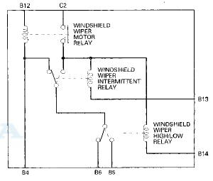
Windshield wiper motor relay: There should be continuity between terminals C2 and B6, when battery power is connected to terminal B12 and C2, and battery ground is connected to terminal B4and B13.
There should be no continuity between terminals C2 and B6, when ground is disconnected from terminal B4.
Windshield wiper intermittent relay: There should be battery voltage between terminals B6 and body ground when battery power is connected to terminals B12 and C2, and battery ground is connected to terminal B4 and B13.
There should be no voltage between terminals B6 and body ground when terminal B13 is disconnected.
Windshield wiper high/low relay: There should be continuity between terminals B4 and B5 when battery power is connected to terminals B12 and C2, and battery ground is connected to terminals B4andB14.
There should be no continuity between terminals B4 and B5, and there should be continuity between terminals B4 and B6 when power is disconnected.
Radiator fan relay, Fan control relay, A /C condenser fan relay
Windshield wiper motor relay. Windshield wiper intermittent relay, Windshield wiper high/low relay
4. If any relays fails the test, replace the relay circuit board.
5. Reinstall all removed parts.
6. Do the battery terminal reconnection procedure (see page 22-91).
 Battery Removal and Installation
NOTE: The battery terminal disconnection and
reconnection procedure (see page 22-91) must be done
before and after doing this procedure- Some systems
store data in memory that is lost when the batt ...
 Ignition Switch
...
See also:
Transmitter Test
NOTE:
• If the doors unlock or lock with the
transmitter, but the
LED on the transmitter does not come on, the LED is
faulty; replace the transmitter.
• If any door is open, you cann ...
Control Locations
Control Locations ...
Circuit Diagram
'10 model w i t h navigation system
'08-09 models with navigation system
Without navigation system with climate control system
With HVAC control system
...