 Honda Accord: MICU Input Test
NOTE: # Before t e s t i n g , t r o u b l e s h o o t the m u l t i p l e x i n t e g r a t e d control unit first, using B-CAN System D i a g n o s i s Test Mode A (see page 22-134).
• Before t e s t i n g , do the gauge c o n t r o l module s e l f - d i a g n o s i s f u n c t i o n (see page 22-332), and make sure the s a f e ty i n d i c a t o r LEDs and B-CAN c o m m u n i c a t i o n line are OK.
Driver's MICU
1. Turn the ignition switch to LOCK (0), and remove the driver's d a s h b o a r d lower cover (see page 20-166).
2. D i s c o n n e c t d r i v e r ' s under-dash fuse/relay box c o n n e c t o r s D, Q, and R.
NOTE: All c o n n e c t o r v i e w s are w i r e side of f e m a l e t e r m i n a l s .
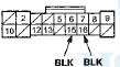
CONNECTOR D(16P)
CONNECTOR Q (20P)
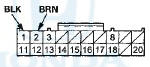
CONNECTOR R (24P)
*: 4-door
3. Inspect the connector and socket terminals to be sure they are all making good contact.
• If the terminals are bent, loose or corroded, repair them as necessary and recheck the system.
• If the terminals look OK, go to step 4 .
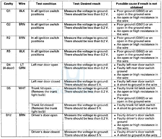
4. Reconnect the connectors to the driver's under-dash fuse/relay box, and do these input tests at the following connector.
• If any test indicates a problem, find and correct the cause, then recheck the system.
• If all the input tests prove OK go to step 5.
Passenger's MICU
5. Turn the ignition switch to LOCK (0), and remove the passenger's kick panel.
• 2-door (see page 20-105) • 4-door (see page 20-107) 6. Disconnect passenger's under-dash fuse/relay box connectors A, E, and G # 1 (or H*2).
*1: LX, LX PZEV, LX-P, LX-P PZEV
*2: Except LX, LX PZEV, LX-P, LX-P PZEV
NOTE: All connector views are wire side of female terminals.
CONNECTOR A (38P)
CONNECTOR G (16P) (LX, LX PZEV, LX-P, LX-P PZEV)
CONNECTOR H (38P) (Except LX, LX PZEV, LX-P, LX-P PZEV)
CONNECTOR E (18P)
*1: 4-door
*2: '08-09 models
7. Inspect the connector and socket terminals to be sure they are all making good contact.
• If the terminals are bent, loose or corroded, repair them as necessary and recheck the system.
• If the terminals look OK, go to step 8.
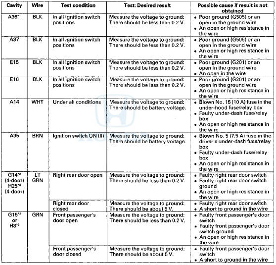
8. Reconnect the connectors to the passenger's under-dash fuse/relay box, and do these input tests at the following connectors.
• If any test indicates a problem, find and correct the cause, then recheck the system.
• If all the input tests prove OK, go to step 9.
*1:'08-09 models
*2: LX, LX PZEV, LX-P, LX-P PZEV
*3: Except LX, LX PZEV, LX-P, LX-P PZEV
9. If multiple failures are found on more than one control unit, replace the driver's under-dash fuse/relay box (includes the driver's MICU).
• USA models (see page 22-86) • Canada models (see page 22-87) If input failures are related to a particular control unit, replace the control unit
 Circuit Diagram
...
 Reminder Systems
...
See also:
Front Door Glass and Regulator
Replacement
NOTE: Put on gloves to protect your hands.
1. Remove the door panel:
- 2-door (see page 20-12)
- 4-door {see page 20-17)
2.2-door: Remove the screws, then remove the door
panel bracket (A).
...
Cable Reel Replacement
Removal
1. Make sure t h e f r o n t w h e e l s are a l i g n e d straight
ahead.
2. Do t h e b a t t e r y t e r m i n a l d i s c o n n e c t i o n procedure
(see
page 22-91), t h e n w a i ...
Controls Near the Steering Wheel
Controls Near the Steering Wheel ...