 Honda Accord: MICU input Test
NOTE: Before testing, troubleshoot the multiplex integrated control unit first, using B-CAN System Diagnosis Test Mode A (see page 22-134).
Driver's MICU
1. Turn the ignition switch to LOCK (0), and remove the driver's dashboard lower cover (see page 20-166).
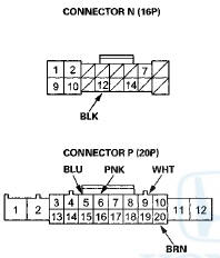
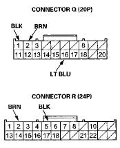
2. Disconnect driver's under-dash fuse/relay box connectors N, P, Q, and R.
NOTE: All connector views are wire side of female terminals.
3. Inspect the connector and socket terminals to be sure they are all making good contact.
• If the terminals are bent, loose or corroded, repair them as necessary and recheck the system.
• If the terminals look OK, go to step 4.
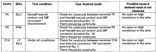
4. With the connectors still disconnected, do these input tests at the following connectors.
• If any test indicates a problem, find and correct the cause, then recheck the system.
• If all the input tests prove OK, go to step 5.

*1: With premium audio system
*2: With HandsFreeLink
*1: With premium audio system
*2: With HandsFreeLink
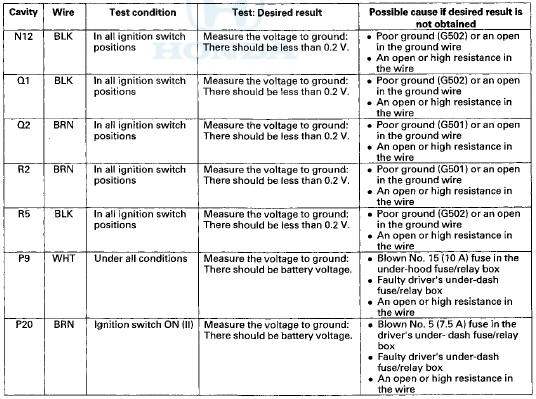
5. Reconnect the connectors to the driver's under-dash fuse/relay box, turn the ignition switch to ON (II), and do these input tests at the following connectors.
• If any test indicates a problem, find and correct the cause, then recheck the system.
• If all the input tests prove OK, go to step 6.
NOTE: These are power and ground tests for the multiplex integrated control unit.
Passenger's MICU
6. Turn the ignition switch to LOCK (0), and remove the passenger's kick panel.
• 2-door (see page 20-105)
• 4-door (see page 20-107)
7. Disconnect passenger's under-dash fuse/relay box connectors A and E.
NOTE: All connector views are wire side of female terminals.
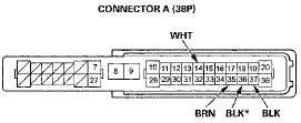
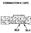
*: "08-09 models
8. Inspect the connector and socket terminals to be sure they are all making good contact.
• If the terminals are bent, loose or corroded, repair them as necessary and recheck the system.
• If the terminals look OK, go to step 9.
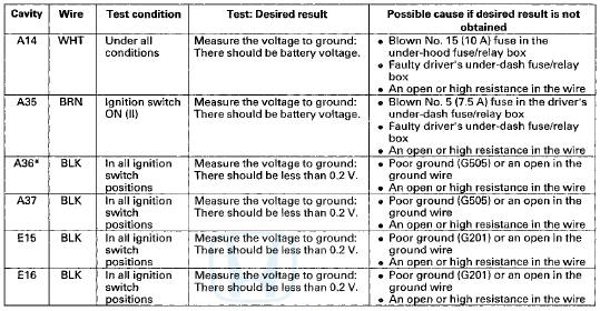
9. Reconnect the connectors to the passenger's under-dash fuse/relay box, turn the Ignition switch to ON (II), and do these input tests at the following connectors.
• If any test indicates a problem, find and correct the cause, then recheck the system.
• If all the input tests prove OK, go to step 10.
*: '08-09 models
10. If multiple failures are found on more than one control unit, replace the driver's under-dash fuse/relay box (includes the driver's MICU).
• USA models (see page 22-86) • Canada models (see page 22-87) If input failures are related to a particular control unit, replace the control unit.
 DTC Troubleshooting
DTC B10A2: Driver's MICU (EEPROM) Error
NOTE: If you are troubleshooting multiple DTCs, be sure
to follow the instructions in B-CAN System Diagnosis
Test Mode A (see page 22-134).
1. Clear the D ...

See also:
Supplemental restraint system (SRS) (if steering maintenance is required)
The Accord SRS includes a driver's airbag in the steering wheel hub, a
passenger's airbag in the dashboard
above the glove box, seat belt tensioners in the front seat belt retractors,
side curtai ...
Light Switches
• Manual Operation
Rotating the light switch turns the lights on
and off, regardless of the position of the
ignition switch*1.
• High beams
Push the lever forward until you hear a click.
...