 Honda Accord: Mainshaft Thrust Clearance Adjustment
Special Tools Required
- Mainshaft Holder 07GAJ-PG20110
- Mainshaft Base 07GAJ-PG20130
1. Remove the 72 mm shim (A) and oil guide plate M from the transmission housing (B).
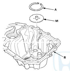
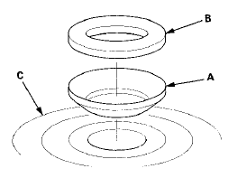
2. Thoroughly clean the 28 mm spring washer (A) and the 28 mm washer (B) before installing them on the clutch housing side ball bearing (C). Note the installation direction of the spring washer.
3. Assemble all of the mainshaft components.
NOTE: Refer to the Exploded View, as needed, during the assembly (see page 13-38).
4. Install the mainshaft assembly into the clutch housing.
5. Place the transmission housing over the mainshaft and onto the clutch housing.
6. Tighten the clutch and transmission housings with several 8 mm bolts.
NOTE: It is not necessary to use sealing agent between the housings for this procedure.
7. Lightly tap on the mainshaft using a plastic hammer.
8. Attach the mainshaft holder (A) and the mainshaft base (B) to the mainshaft as follows: - Back out the mainshaft holder bolt (C), and loosen the two hex bolts (D).
- Fit the holder over the mainshaft so its lip is towards the transmission.
- Align the mainshaft holder lip around the groove at the inside of the mainshaft splines, then tighten the hex bolts.
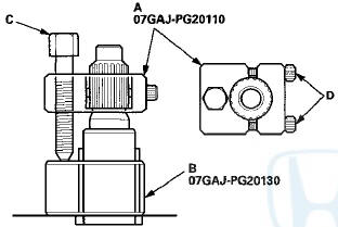
9. Fully seat the mainshaft by tapping its end using a plastic hammer.
10. Thread the mainshaft holder bolt in until it just contacts the wide surface of the mainshaft base.
11. Zero a dial gauge (A) on the end of the mainshaft
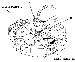
12. Turn the mainshaft holder bolt (B) clockwise; stop turning when the dial gauge has reached its maximum movement. The reading on the dial gauge is the amount of mainshaft thrust clearance.
NOTE: Do not turn the mainshaft holder bolt more than 60 degrees after the needle of the dial gauge stops moving. Applying more pressure with the mainshaft holder bolt could damage the transmission.
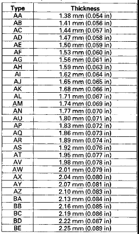
13. If the reading is within the standard, the clearance is correct. If the reading is not within the standard, select the appropriate shim needed from the table, and recheck the thrust clearance.
Standard: 0.11-0.17 mm (0.004-0.007 in)
(Example) Measure reading: 1.93 mm (0.076 in)
1.93 - 0.14 (0.076-0.006) = 1.79 mm (0.070 in)
Select the shim closest to the amount calculated, for example the 1.80 mm (0.071 in) shim.
14. With oil guide plate M and the appropriate size shim installed in the transmission housing, check the thrust clearance again to verity the clearance is within the standard.
72 mm Shim

 Countershaft Bearing Replacement
Special Tools Required
- Oil Seal Driver, 65 07JAD-PL90100
- Adjustable Bearing Puller, 20-”40 mm 07736-A01000B
- Slide Hammer 3/8"-16 UNF, commercially available
1. Remove the bearing ...
 Transmission Reassembly
NOTE: Prior to reassembly, clean all the parts in solvent,
dry them, and apply MTF to any contact surfaces.
1. Install the magnet (A) and the differential assembly
(B).
NOTE: Clean the magnet ...
See also:
Symptom Troubleshooting
Index
...
Status Log
If you suspect there is a immobilizer system problem, check the status log.
1. Connect the HDS to the data link connector.
2. Turn the ignition switch to ON (II).
3. On the HDS screen, at MAI ...
Setting the Clock
On models without navigation system
To set the time, press the CLOCK
button until you hear a beep. The
displayed time begins to blink.
Change the hours by pressing the H
(hour) button until th ...