 Honda Accord: Knuckle/Hub/Wheel Bearing Replacement
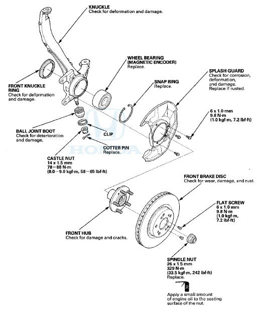
Exploded View
Special Tools Required
- Ball Joint Thread Protector, 14 mm 07AAE-SJAA100
- Ball Joint Thread Protector, 12 m m 07AAF-SDAA100
- Ball Joint Thread Protector, 10 m m 07AAF-SECA120
-Ball Joint Remover, 28 mm 07MAC-SL0A202
- Hub Dis/Assy Tool 07GAF-SD4A100
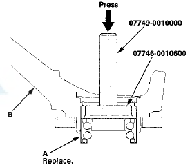
- Attachment, 72 x 75 mm 07746-0010600
- Driver Handle, 15 x 135L 07749-0010000
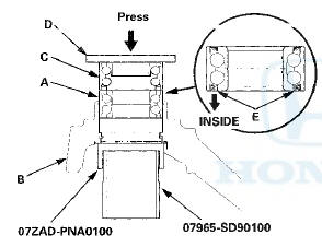
- Oil Seal Driver Attachment, 96 mm 07ZAD-PNA0100
- Support Base 07965-SD90100
Knuckle/Hub Replacement
1. Raise and support the vehicle (see page 1-13).
2. Remove the wheel nuts and the front wheel.
3. Remove the brake hose bracket mounting bolt (A).
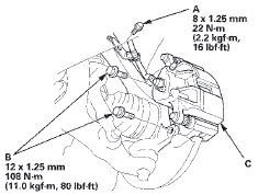
4. Remove the brake callper bracket mounting bolts (B), then remove the caliper assembly (C) from the knuckle. To prevent damage to the caliper assembly or the brake hose, use a short piece of wire to hang the caliper assembly from the undercarriage. Do not twist the brake hose excessively.
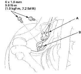
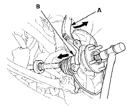
5. Remove the wheel speed sensor harness bracket (A) and the wheel speed sensor (B) from the knuckle. Do not disconnect the wheel speed sensor connector.
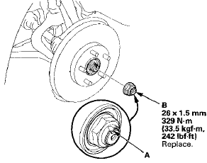
6. Pry up the stake (A) on the spindle nut (B), then remove the nut.
7. Remove the front brake disc (see page 19-21).
8. Check the front hub for damage and cracks.
9. Remove the cotter pin (A) from the tie-rod end ball joint, then remove the nut (B).
NOTE: During installation, install the new cotter pin after tightening the nut, and bend its end as shown.
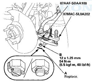
10. Disconnect the tie-rod end ball joint from the knuckle using the ball joint thread protector and the ball joint remover (see page 18-10).
11. Remove the cotter pin (A) from the knuckle ball joint, then remove the castle nut (B).
NOTE: During installation, insert the new cotter pin into the ball joint pin hole from the front to the rear of the vehicle, and bend its end as shown. Check the ball joint pin hole direction before connecting the ball joint.
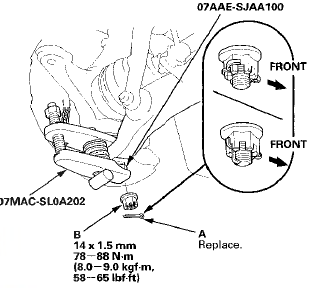
12. Disconnect the knuckle ball joint from the lower arm using the ball joint thread protector and the ball joint remover (see page 18-10).
NOTE: - Be careful not to damage the ball joint boot when installing the remover.
- Do not force or hammer on the lower arm, or pry between the lower arm and the knuckle. You could damage the ball joint.
13, Remove the cotter pin (A) from the upper arm ball joint, then remove the castle nut (B).
NOTE: During installation, insert the new cotter pin into the ball joint pin hole from the front to the rear of the vehicle, and bend its end as shown. Check the ball joint pin hole direction before connecting the ball joint.
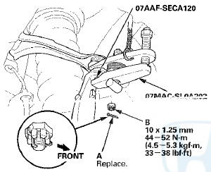
14. Disconnect the upper arm ball joint from the knuckle using the ball joint thread protector and the ball joint remover (see page 18-10).
15. Pull the knuckle (A) outward, and separate the outboard joint (B) from the front hub a plastic hammer outward, then remove the knuckle/hub.
NOTE: - Do not pull the driveshaft end outward. The driveshaft inboard joint may come apart.
- During installation, apply grease to the mating surfaces of the wheel bearing and the driveshaft outboard joint (see step 1 on page 16-19).
16. Install the knuckle/hub in the reverse order of removal, and note these items: - First install all of the components, and lightly tighten the bolts and the nuts, then raise the suspension to load it with the vehicle's weight before fully tightening to the specified torque. Do not place the jack against the ball joint pin of the knuckle.
- Be careful not to damage the ball joint boot when connecting the knuckle.
- Before connecting the ball joint, degrease the threaded section and the tapered portion of the ball joint pin, the ball joint connecting hole, and the threaded section and the mating surfaces of the castle nut.
- Torque the castle nut to the lower torque specification, then tighten it only far enough to align the slot with the ball joint pin hole. Do not align the castle nut by loosening it.
- Use a new spindle nut on reassembly.
- Before installing the spindle nut, apply a small amount of engine oil to the seating surface of the nut. After tightening, use a drift to stake the spindle nut shoulder against the driveshaft.
- Before installing the brake disc, clean the mating surfaces of the front hub and the inside of the brake disc.
- Before installing the wheel, clean the mating surfaces of the brake disc and the inside of the wheel.
17. Check the wheel alignment, and adjust it if necessary (see page 18-5).
Wheel Bearing Replacement
1 . Remove the knuckle/hub.
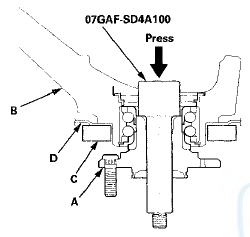
2. Separate the hub (A) from the knuckle (B) using the hub dis/assy tool and a hydraulic press. Hold the knuckle with the attachment (C) of the hydraulic press or equivalent tool. Be careful not to damage or deform the splash guard (D). Hold onto the hub to keep it from falling when pressed clear.
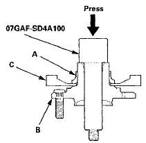
3. Press the wheel bearing inner race (A) off of the hub (B) using the hub dis/assy tool, a commercially available bearing separator (C), and a press.
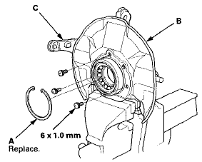
4. Remove the snap ring (A) and the splash guard (B) from the knuckle (C).
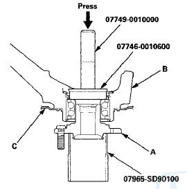
5. Press the wheel bearing (A) out of the knuckle (B) using the attachment, the driver handle, and a press.
6. Wash the knuckle and the hub thoroughly in high flash point solvent before reassembly.
7. Press a new wheel bearing (A) into the knuckle (B) using the old bearing (CL a steel plate (D), the attachment the support base, and a press. .
NOTE: - Install the wheel bearing with the wheel speed sensor magnetic encoder (E) (brown color), toward the inside of the knuckle.
- Remove any oil, grease, dust, metal debris, and other foreign material from the magnetic encoder surface.
- Keep any magnetic tools away from the magnetic encoder surface.
- Be careful not to damage the magnetic encoder surface when you insert the wheel bearing.
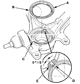
8. Check the front knuckle ring (A) for damage or deformation, and replace it If necessary.
NOTE: When installing the new front knuckle ring, position the knuckle ring notch portion ( B ) toward cut out (C) near the ball joint in the knuckle, and align the center of the knuckle ring ledge portion ( D ) with the center of the wheel speed sensor hole (E) on the knuckle as shown.
9. Install the new snap ring (A) securely in the knuckle (B).
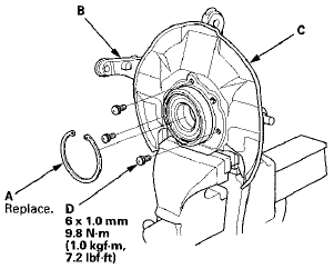
10. Install the splash guard (C), and tighten the screws ( D ) to the specified torque.
11. Install the hub (A) onto the knuckle (B) using the attachment the driver handle, the support base, and a hydraulic press. Be careful not to damage the splash guard (C).
12. Install the knuckle/hub.
 Front Suspension
...
 Upper Arm Replacement
Special Tools Required
-Ball Joint Thread Protector, 10 mm
07AAF-SECA120
- Ball Joint Remover, 28 mm 07MAC-SL0A202
1. Raise and support the vehicle (see page 1-13).
2. Remove the front wheel.
...
See also:
USB Flash Memory Device Error Messages (Models with navigation system)
If you see an error message in the
center display while playing a USB
flash memory device, find the
solution in the chart to the right. If
you cannot clear the error message,
take your vehic ...
Rear Seat Access
Driver’s Side
On all V6 models and 4-cylinder EX-L
model
To get into the rear seat on the
driver’s side, open the door and pull
the release lever up on the side of
the seat-back. The s ...
Audio System Basic Operation
To use the audio system function, the power mode must be in ACCESSORY or ON.
Use the selector knob, DISP and BACK
buttons to access some audio functions.
Press to switch between the
normal ...