 Honda Accord: HVAC Control Power and Ground
Circuit Troubleshooting
1. Check the No. 16 (7.5 A) fuse in the driver's under-dash fuse/ relay box.
Is the fuse OK? YES
-Go to step 2.
NO
-Replace the fuse, and recheck. If the fuse blows again, check for a short in the No. 16 (7.5 A) fuse circuit.
2. Disconnect the HVAC control unit 24P connector.
3. Turn the ignition switch to ON (II).
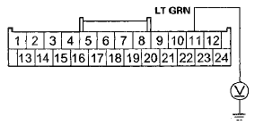
4. Measure the voltage between HVAC control unit 24P connector terminal No. 11 and body ground.
HVAC CONTROL UNIT 24P CONNECTOR

Wire side of female terminals
Is there battery voltage? YES
-Go to step 5.
NO
-Repair an open in the wire between the No. 16 (7.5 A) fuse in the driver's under-dash fuse/relay box and the HVAC control unit.
5. Turn the ignition switch to LOCK (0).
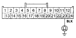
6. Check for continuity between HVAC control unit 24P connector terminal No. 23 and body ground.
HVAC CONTROL UNIT 24P CONNECTOR

Wire side of female terminals
Is there continuity? YES
-Check for loose wires or poor connections at the HVAC control unit 24P connector. If the connections are good, substitute a known-good HVAC control unit (see page 21-65), and recheck.
NO
-Check for an open in the wire between the HVAC control unit and body ground. If the wire is OK, check for poor ground at G401 (see page 22-40).
 Recirculation Control Motor Circuit
Troubleshooting
908-09 models 4-door with A/T and '10 model
with AT
1. Check the No. 16 (7.5 A) fuse in the driver's
under-dash fuse/ relay box.
Is the fuse OK?
YES-Go to step 2.
NO-Replace the fuse, and re ...
 A/C Condenser Fan Circuit
Troubleshooting
NOTE:
• Do not use this troubleshooting procedure if the
radiator fan and/or the A/C compressor is inoperative.
Refer to the symptom troubleshooting index.
• Before doing symptom tro ...
See also:
Driver and Passenger Safety
This section gives you important
information about how to protect
yourself and your passengers. It
shows you how to use seat belts. It
explains how your airbags work. And
it tells you how to ...
CD Player
If a disc error occurs, you may see the following error messages.
...
Fuel Information
• Fuel recommendation
Use of a lower octane gasoline can cause a persistent, heavy metallic
knocking noise
that can lead to engine damage.
• Top tier detergent gasoline
Because the level ...
