 Honda Accord: General Troubleshooting Information
Intermittent Failures
The term Intermittent failure means a system may have had a failure, but it checks OK now. If the malfunction indicator lamp (MIL) on the dash does not come on, check for poor connections or loose terminals at all connectors related to the circuit that you are troubleshooting. If the MIL was on but then went out, the original problem may have been intermittent.
Service Information
Periodically, new ECM/PCM software or new service procedures may become available. Always check online for the latest software or service information related to the DTCs or symptoms you are troubleshooting.
Opens and Shorts
Open and short are common electrical terms. An open is a break in a wire or at a connection. A short is an accidental connection of a wire to ground or to another wire. In simple electronics, this usually means something won't work at all. With complex electronics (such as ECMs or PCMs) this can sometimes mean something works, but not the way it's supposed to.
How to Use the HDS (Honda Diagnostic System)
It the MIL (malfunction indicator lamp) has come on
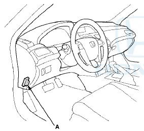
1. Start the engine, and check the MIL (A).
NOTE: If the ignition switch is turned to ON (II), and the engine is not started, the MIL stays on for 15-”20 seconds (see page 11-65).
2. If the MIL stays on, connect the HDS to the data link connector (DLC) (A) located under the driver's side of the dashboard.
3. Turn the ignition switch to ON (II).
4. Make sure the HDS communicates with the ECM/PCM and other vehicle systems. If it doesn't, go to the DLC circuit troubleshooting (see page 11-181).
5. Check the diagnostic trouble code (DTC) and note it.
Also check the freeze data and/or on-board snapshot data, and download any data found. Then refer to the indicated DTCs troubleshooting, and begin the appropriate troubleshooting procedure.
NOTE: - Freeze data indicates the engine conditions when the first system malfunction, misfire, or fuel trim malfunction that activated the MIL was detected.
- The HDS can read the DTC, the freeze data, the on-board snapshot, the current data, and other engine control module (ECM) or powertrain control module (PCM) data.
- For specific operations, refer to the user's manual that came with the HDS.
6. If no DTCs are found, go to the MIL circuit troubleshooting (see page 11-180).
If the MIL did not stay on
If the MIL did not stay on but there is a driveability problem, do the symptom troubleshooting.
If you can't duplicate the DTC
Some of the troubleshooting requires you to reset the ECM/PCM and try to duplicate the DTC. If the problem is intermittent and you can't duplicate the code, do not continue through the procedure. To do so will only result in confusion and possibly, a needlessly replaced ECM/PCM.
HDS Clear Command
The ECM/PCM stores various specific data to correct the system even if there is no electrical power such as when the battery negative terminal or No. 17 Fl MAIN (15 A) fuse are disconnected. Stored data based on failed parts should be cleared by using the CLEAR COMMAND of the HDS, if parts are replaced.
The HDS has three kinds of clear commands to meet this purpose. They are DTC clear, ECM/PCM reset, and CKP pattern clear. The DTC clear command erases all stored DTC codes, freeze data, on-board snapshot, and readiness cddes. This must be done with the HDS after reproducing the DTC during troubleshooting.
The ECM/PCM reset command erases all stored DTC codes, freeze data, on-board snapshot, readiness codes, and all specific data to correct the system except CKP pattern. If the CKP pattern data in the ECM/PCM was cleared, you must do the CKP pattern learn procedure.
The CKP pattern clear command erases only CKP pattern data. This command is for repair of a misfire or the CKP sensor.
Scan Tool Clear Command
If you are using a generic scan tool to clear commands, be aware that there is only one setting for clearing the ECM/PCM, and it clears all commands at the same time (CKP pattern learn, idle learn, readiness codes, freeze data, on-board snapshot, and DTCs). After you clear all commands, you then need to do these procedures, in this order: ECM/PCM idle learn procedure; (see page 11-293) CKP pattern learn procedure; test-drive to set readiness codes to complete (see page 11-65).
DTC Clear
1. Clear the DTC with the HDS while the engine is stopped.
2. Turn the ignition switch to LOCK (0).
3. Turn the ignition switch to ON (II), and wait 30 seconds.
4. Turn the ignition switch to LOCK (0), and disconnect the HDS from the DLC.
ECM/PCH Reset
1. Reset the ECM/PCM with the HDS while the engine is stopped.
2. Turn the ignition switch to LOCK (0).
3. Turn the ignition switch to ON (II), and wait 30 seconds.
4. Turn the ignition switch to LOCK (0), and disconnect the HDS from the DLC.
5. Do the ECM/PCM idle learn procedure (see page 11-293).
CKP Pattern Clear/CKP Pattern Learn
Clear/Learn Procedure (with the HDS)
1. Connect the HDS to the data link connector (DLC) (A) located under the driver's side of the dashboard.
2. Turn the ignition switch to ON (II).
3. Make sure the HDS communicates with the ECM/PCM and other vehicle systems. If it doesn't, go to the DLC circuit troubleshooting (see page 11-181).
4. Select CRANK PATTERN in the ADJUSTMENT MENU with the HDS.
5. Select CRANK PATTERN LEARNING with the HDS, and follow the screen prompts.
Learn Procedure (without the HDS)
1. Start the engine. Hold the engine speed at 3,000 rpm without load (A/T in P or N, M/T in neutral) until the radiator fan comes on.
2. Test-drive the vehicle on a level road: Decelerate (with the throttle fully closed) from an engine speed of 2,500 rpm down to 1,000 rpm with the A/T in 2, or the M/T in 2nd.
3. Repeat step 2 several times.
4. Turn the ignition switch to LOCK (0).
5. Turn the ignition switch to ON (II), and wait 30 seconds.
How to End a Troubleshooting Session (required after any troubleshooting)
1. Reset the ECM/PCM with the HDS.
2. Do the ECM/PCM idle learn procedure (see page 11-293).
3. Turn the ignition switch to LOCK (0).
4. Disconnect the HDS from the DLC.
NOTE: The ECM/PCM is part of the immobilizer system. If you replace the ECM/PCM, for the engine to start, you must use the HDS to instruct the new ECM/PCM and the immobilizer-keylwss control unit to recognize each other's unique serial code.
How to Troubleshoot Circuits at the ECM/PCM Connectors
NOTE: The ECM/PCM overwrites data and monitors the EVAP system for about 40 minutes after the ignition switch is turned to LOCK (0). Jumping the SCS line after turning the ignition switch to LOCK (0) cancels this function. Disconnecting the ECM/PCM during this function, without jumping the SCS line first, can damage the ECM/PCM.
1. Jump the SCS line with the HDS.
2. Remove the bolts (D).
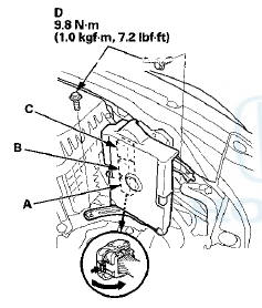
3. Disconnect ECM/PCM connectors A, B, and C.
4. When diagnosis/troubleshooting is done at the ECM/PCM connector, use the terminal test port (A) above the terminal you need to check.
5. Connect one side of the patch cord's terminals (A) to a commercially available digital multimeter (B), and connect the other side of the terminals (C) to a commercially available banana jack (Pomona Electronics Tool No. 3563 or equivalent) (D).
6. Gently contact the pin probe (male) at the terminal test port from the terminal side. Do not force the tips into the terminals.

- For accurate results, always use the pin probe (male).
- To prevent damage to the connector terminals, do not insert test equipment probes, paper clips, or other substitutes as they can damage the terminals.
Damaged terminals cause a poor connection and an incorrect measurement.
- Do not puncture the insulation on a wire. Punctures can cause poor or intermittent electrical connections.
Substituting the ECM/PCM
Special Tools Required
Honda diagnostic system (HDS) tablet tester
Honda Interface Module (HIM) and an iN workstation with the latest HDS software version
HDS pocket tester
GNA600 and an iN workstation with the latest HDS software version
Any one of the above updating tools can be used.
NOTE: Use this procedure when you have to substitute a known-good ECM/PCM during troubleshooting procedure.
1. Connect the HDS to the data link connector (DLC) (A) located under the driver's side of the dashboard.
2. Turn the ignition switch to ON (II).
3. Make sure the HDS communicates with the ECM/PCM and other vehicle systems. If it doesn't, go to the DLC circuit troubleshooting (see page 11-181). If you are returning from DLC circuit troubleshooting, skip steps 4 and 5, and the clean the throttle body after substituting the ECM/PCM (see page 11-332).
4. Select the INSPECTION MENU with the HDS.
5. Select the ETCS TEST, then select the TP POSITION , CHECK, and follow the screen prompts.
NOTE: If the TP POSITION CHECK indicates FAILED, continue this procedure.
6. Turn the ignition switch to LOCK (0).
7. Jump the SCS line with the HDS.
8. Do the battery removal procedure (see page 22-92).
9. Remove the bolts (D).
10. Disconnect ECM/PCM connectors A, B, and C, then remove the ECM/PCM assembly (E).
NOTE: ECM/PCM connectors A, B, and C have
symbols (A= , B=
, B=
, C= ) embossed on them for
identification.
11.Remove the cover (A) and the bracket (B) from the ECM/PCM (C).
12. Install a known-good ECM/PCM in the reverse order of removal.
13. Do the battery installation procedure (see page 22-92).
14. Turn the ignition switch to ON (II).
NOTE: DTC P0630 (VIN Not Programmed or Mismatch) may be stored because the VIN has not been programmed into the ECM/PCM; ignore it, and continue this procedure.
15. Manually input the VIN to the ECM/PCM with the HDS.
16. Select the IMMOBI SYSTEM with the HDS.
17. Enter the immobilizer ECM/PCM code that you got from iN, and use the ECM/PCM replacement procedure in the IMMOBI MENU of the HDS; it allows you to start the engine.
18. If the TP POSITION CHECK failed in step 5, clean the throttle body (see page 11-332).
19. Reset the ECM/PCM with the HDS.
20. Update the ECM/PCM if it does not have the latest software (see page 11-203).
21. Do the ECM/PCM idle learn procedure (see page 11-293).
22. Do the CKP pattern clear/CKP pattern learn procedure.
OBD Status
The OBD status shows the current system status of each DTC and all of the parameters. This function is used to see if the repair was successfully completed. The results of diagnostic tests for the DTC are displayed as: - PASSED: The on board diagnosis is successfully finished.
- FAILED: The on board diagnosis has finished but failed.
- EXECUTING: The vehicle is in enable criteria conditions of the DTC and the on board diagnosis is running.
- NOT COMPLETED: The on board diagnosis was running but is out of the enable conditions of the DTC.
Р’В« OUT OF CONDITION: The vehicle has stayed out of the zr.zblz ccr.ditbr.c cf the DTC.
 Special Tools
...
 DTC Troubleshooting Index
NOTE: The above DTCs are indicated when the PGM-FI system is selected with
the HDS. Some automatic transmission DTCs cause the MIL to
come on. If the MIL is on and no DTCs are indicated in the PG ...
See also:
Malfunction Indicator Lamp
If the indicator comes on
while driving, it means one
of the engine’s emissions control
systems may have a problem. Even
though you may feel no difference in
your vehicle’s performance ...
Power Door Mirrors
You can adjust the door mirrors when the
ignition switch is in ON .
• Mirror position adjustment
L/R selector switch: Select the left or right
mirror. After adjusting the mirror, return the ...
Component Location Index - Front Door
2-door
4-door
...