 Honda Accord: Function Test
NOTE; • With climate control: Before testing, troubleshoot the B-CAN System Diagnosis Test Mode A (see page 22-134).
• Before testing, check the No. 4 (40 A) fuse in the under-hood fuse/relay box and the No. 16 (7.5 A) fuse in the driver's under-dash fuse/relay box.
• Be careful not to scratch or damage the defogger wires with the tester probe.
1. Turn the ignition switch to ON (II), then turn the rear window defogger switch ON.
2. Measure the voltage between the positive terminal (A) and body ground. There should be battery voltage.
• If there is no voltage, check for:
- Faulty climate control unit, driver's climate control switch ('10 model), passenger's climate control switch ('08-09 models), or HVAC control unit.
- An open or high resistance in the GRN wire to the positive terminal.
• If there is voltage, go to step 3.
3. Measure the voltage between the negative terminal (B) and body ground. There should be less than 0.2 V.
If there is greater than 0.2 V, check for an open in the BLK wire or poor ground (G801). If there is 0.2 V or less, go to step 4.
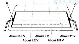
4. Touch the voltmeter positive probe along each defogger wire, and the negative probe to the negative terminal.
• If the voltage is as specified, the defogger wire up to that point is OK.
• If the voltage is not as specified, repair the defogger wire.
- If voltage is more than specified at one of the points, there is a break in the negative half of the wire.
- If voltage is less than specified at one of the points, there is a break in the positive half of the wire.
 Circuit Diagram
'10 model w i t h navigation system
'08-09 models with navigation system
Without navigation system with climate control system
With HVAC control system
...
 Defogger Wire Repair
NOTE: To make an effective repair, the broken section
must be no longer than 1.0 in (25 mm).
1. Lightly rub the area around the broken section (A)
with fine steel wool, then clean it with isoprop ...
See also:
Adjusting the Sound
Press the MENU button to display
the sound settings. Turn the selector
knob to select an appropriate setting:
bass, treble, fader, balance, SUBW*
(subwoofer) and SVC (speedsensitive
volume ...
Maintenance Main Items and Sub Items
All maintenance items displayed on
the information display are in code.
For an explanation of these
maintenance codes. ...
Specifications (4-cylinder models)
Dimensions
Dimensions
Weights
Weights
Air Conditioning
Air Conditioning
Engine
Engine
Seating Capacities
Seating Capacities
Capacities
Capacities
* 1: Including the coolant in ...