 Honda Accord: Front Seat Frame Replacement
Driver's Seat
Honda Accord: Front Seat Frame Replacement
Driver's Seat
Special Tools Required
KTC Trim Tool Set SOJATP2014*
*Available through the Honda Tool and Equipment Program; call 888-424-6857
SRS components are located in this area. Review the SRS component locations, 2-door (see page 24-23), 4-door (see page 24-21) and the precautions and procedures (see page 24-25) before doing repairs or service.
NOTE: - Put on gloves to protect your hands.
- Use the appropriate tool from the KTC trim tool set to avoid damage when removing components.
- If the side airbag has deployed, replace the seat frame and related parte with new onee.
1. Remove the front seat (see page 20-194).
2. Remove these items: - Front seat-back cover/pad: - 2-door (see page 20-213) - 4-door (see page 20-221) - Front seat cushion cover/pad: - 2-door (see page 20-226) - 4-door (see page 20-234) - Seat belt buckle: - 2-door (see page 24-7) - 4-door (see page 24-13) - Seat position sensor (see page 24-239) - Side airbag (see page 24-215)
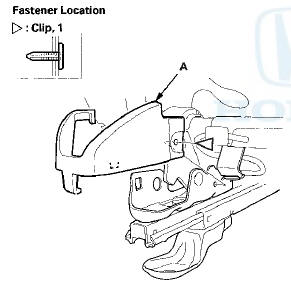
3. Detach the clips, then remove the outer cover (A).
10-way power seat

Manual height adjustable seat
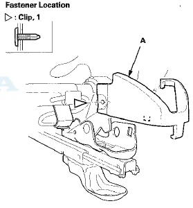
4. Detach the clip(s), then remove the inner cover (A).
10-way power seat
Manual height adjustable seat
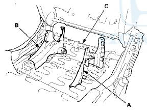
5. Remove the recline inner cover (A) and the center inner cover (B) from the seat frame (C).
10-way power seat

Manual height adjustable seat
6.10-way power seat: Remove the rear gear outer cover (A) and the rear gear inner cover (B).
7. Install the seat frame in the reverse order of removal, and note these items: - If the clips are damaged or stress-whitened, replace them with new ones.
- Push the clips into place securely.
 Rear Seat Access Cable Replacement
2-door Passenger's Seat
NOTE:
- Put on gloves to protect your hands.
- Take care not to kink the rear seat access cable.
- The right rear seat access cable is shown; the left rear
seat access ...
 Front Seat Frame Replacement - Passenger's Seat
Special Tools Required
KTC Trim Tool Set SOJATP2014*
*Available through the Honda Tool and
Equipment
Program; call 888-424-6857
2-door
SRS components are located in this area. Review the
SRS c ...
See also:
Tire and Wheel Replacement
Replace your tires with radials of the same size, load range, speed rating,
and
maximum cold tire pressure rating (as shown on the tire’s sidewall). Using tires
of a
different size or constr ...
Circuit Diagram
...
Starter Removal and
Installation
Removal
1 Do the battery removal procedure (see page 22-92).
2. Remove the intake manifold (see page 9-4).
3. Disconnect the positive starter cable (A) from the B
terminal, and the S terminal ...