 Honda Accord: Frame Repair Chart
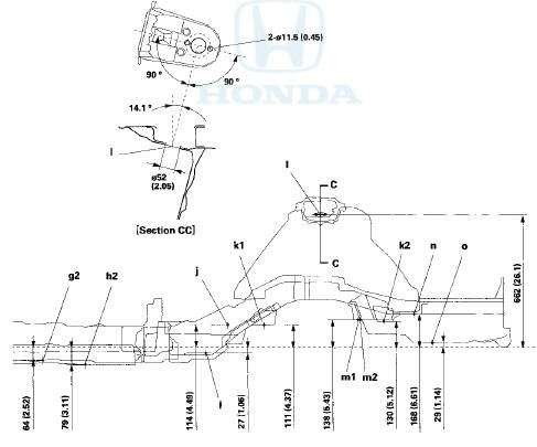
Top View
g2 Front floor locating hole 025 (0.98) rear
h2 Front floor tunnel frame locating hole 013 (0.51) rear
i Rear frame A locating hole 025 (0.98)
j Rear floor locating hole 025 (0.98)
k1 For rear subframe mount 028.2 (1.03) front
k2 For rear subframe mount 026.2 (1 .В©3) rear
I Rear damper center hole 052 (2.05

Side View
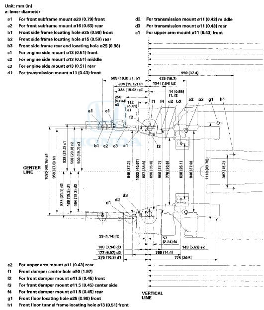
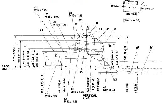
Unit: mm (in)
0: Inner diameter
al For front subframe mount 02В© (0.79) front
a2 For front subframe mount 018 (0.S3) rear
bl Front side frame locating hole 025 (0.98) front
b2 Front side frame locating hole 015 (0.59) rear
b3 Front side frame rear end locating hole 025 (0.98)
cl For engine side mount 013 (0.51) front
c2 For engine side mount 013 (0.51) middle
c3 For engine side mount 013 (0.51) rear
dl For transmission mount 011 (0.43) front
d2 For transmission mount 011 (0.43) middle
d3 For transmission mount 011 (0.43) rear
el For upper arm mount 011 (0.43) front
e2 For upper arm mount 011 (0.43) rear
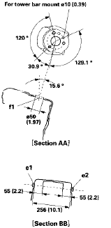
f 1 Front damper center hole 050 (1.97)
f2 For front damper mount 011.5 (0.45) front
f3 For front damper mount 011.5 (0.45) center side
f4 For front damper mount 011.5 (0.45) rear
g1 Front floor locating hole 025 (0.98) front
hi Front floor tunnel frame locating hole 013 (0.51) front
g2 Front floor locating hole 025 (0.98) rear
h2 Front floor tunnel frame locating hole 013 (0.51) rear
I Rear frame A locating hole 025 (0.98)
j Rear floor locating hole 025 (0.98)
kl For rear subframe mount 026.2 (1.03) front
k2 For rear subframe mount 026.2 (1.03) rear
I Rear damper center hole 052 (2.05)
ml Rear floor cross-member locating hole 015 (0.59) right side
m2 Rear floor cross-member locating hole 015 (0.59) left side
n Rear frame B locating hole 025 (0.98)
o Spare tire pan locating hole 025 (0.98)
SUPPLEMENTAL RESTRAINT SYSTEM (SRS) (If HVAC maintenance is required)
The Accord SRS Includes a driver's airbag In the steering wheel hub, a passenger's airbag In the dashboard above the glove box, seat belt tensioners In the front seat belt retractors, side curtain airbags In the sides of the roof, and side airbags in the front seat-backs. Information necessary to safely service the SRS is included in this Service Manual. Items marked with an asterisk (*) on the contents page include or are located near SRS components. Servicing, disassembling, or replacing these items requires special precautions and tools, and should be done by an authorized Honda dealer.
- To avoid rendering the SRS inoperative, which could lead to personal injury or death in the event of a severe frontal or side collision, all SRS service work should be done by an authorized Honda dealer.
- Improper service procedures, including incorrect removal and installation of the SRS, could lead to personal injury caused by unintentional deployment of the airbags, side airbags, and/or side curtain airbags.
- Do not bump or impact the SRS unit, front impact sensors, side impact sensors, or rear safing sensor, especially when the ignition switch is in ON (II), or for at least 3 minutes after the ignition switch is turned to LOCK (0); otherwise, the system may fail in a collision, or the airbags may deploy.
- SRS electrical connectors are identified by yellow color coding. Related components are located in the steering column, center console, dashboard, dashboard lower cover, in the dashboard above the glove box, in the front seats, in the roof side, and around the floor. Do not use electrical test equipment on these circuits.
 Subframe Replacement
Special Tools Required
Subframe Alignment Pin 070AG-SJAA10S
Front Subframe Torque
After removing the subframe mounting bolts, the front subframe middle rubber
mount mounting bolts, the front
sub ...

See also:
Engine Oil Filter Replacement
Special Tools Required
Oil Filter Wrench 07 AAA-PLC A100
1. Drain the engine oil (see page 8-11).
2. Remove the oil filter with the oil filter wrench.
3. Inspect the filter to make sure the ru ...
Under-floorTWC Removal/Installation
1. Raise the vehicle on a lift.
2. Remove the exhaust pipe hangers (A).
3. Remove the under-floor TWC (B).
4. Install the parts in the reverse order of removal with
new gaskets (C) and new s ...
General Troubleshooting Information
How to Check for DTCs with the Honda
Diagnostic S f stem (HDS)
When the powertrain control module (PCM) senses an
abnormality in the input or output system, the D
indicator (A) in the gauge contro ...