 Honda Accord: Fan Controls
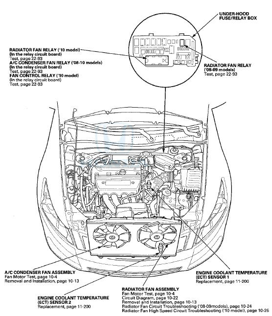
Component Location Index
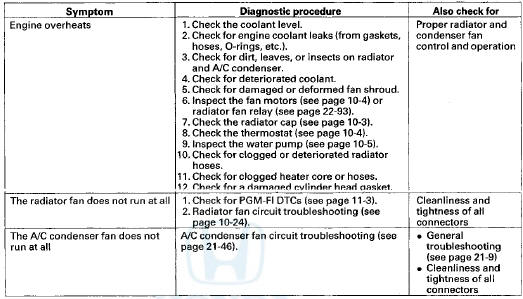
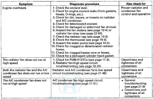
Symptom Troubleshooting Index
'08-09 models
10 model
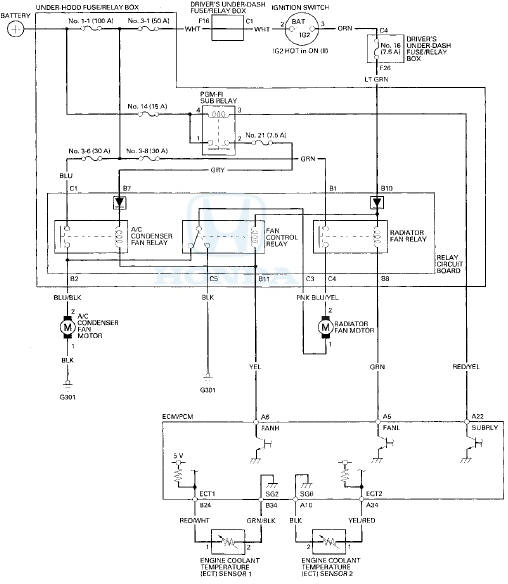
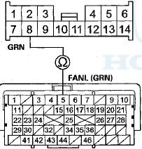
Circuit Diagram
'08-09 models
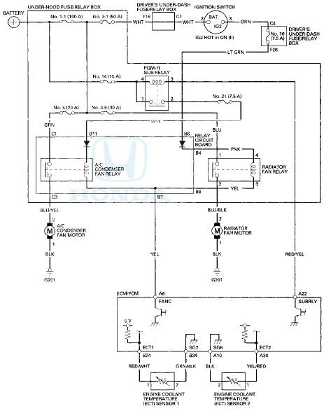
'10 model
Radiator Fan Circuit Troubleshooting
'08-09 models
1. Check the No. 3 - 6 (30 A) fuse in the under-hood fuse/relay box and No. 16 (7.5 A) fuse in the driver's under-dash fuse/relay box.
Are the fuses OK? YES-Go to step 2.
NO-Replace the fuse(s) and recheck. If the fuse continues to blow, locate and repair the short in the circuit between the under-hood fuse/relay box and the radiator fan motor and driver's under-dash fuse/relay box connector terminal F26 and under-hood fuse/relay box connector terminal B6.
2. Remove the radiator fan relay and disconnect and remove the relay circuit board from the under-hood fuse/relay box, and test it (see page 22-93).
Is the relay and/or the relay circuit board OK? YES-Go to step 3.
NO-Replace the radiator fan relay and/or the relay circuit board.
3. Measure the voltage between radiator fan relay 4P socket terminal No. 1 and body ground.
RADIATOR FAN RELAY 4P SOCKET
Terminal side of female terminals
Is there battery voltage? YES-
Go to step 4.
NO
-Replace the under-hood fuse/relay box.
4. Connect radiator fan relay 4P socket terminals No. 1 and No. 2 with a jumper wire.
RADIATOR FAN RELAY 4P SOCKET
Terminal side of female terminals
YES-Go to step 9.
NO-Go to step 5.
5. Test the radiator fan motor (see page 10-4).
Is the motor OK? YES-Go to step 6.
NO-Replace the radiator fan motor (see page 10-13).
6. Disconnect the radiator fan motor 2P connector.
7. Check for continuity between radiator fan relay 4P socket terminal No. 2 and radiator fan motor 2P connector terminal No. 2.
RADIATOR FAN RELAY 4P SOCKET
Terminal side of female terminals
RADIATOR FAN MOTOR 2P CONNECTOR
Wire side of female terminals
Is there continuity? YES-Go to step 8.
NO-Repair open in the wire between the under-hood fuse/relay box and radiator fan motor 2P connector terminal No. 2.
8. Check for continuity between radiator fan motor 2P connector terminal No. 1 and body ground.
RADIATOR FAN MOTOR 2P CONNECTOR
Wire side of female terminals
Is there continuity? YES-Check for poor connections or loose terminals at the under-hood fuse/relay box, the radiator fan motor and body ground G201. NO-Repair open in the wire between radiator fan motor 2P connector terminal No. 1 and body ground.
If the wire is OK, check for a poor ground at G201 . 9. Disconnect the jumper, and turn the ignition switch to ON (II). Check for voltage between radiator fan relay 4P socket terminal No. 4 and body ground.
RADIATOR FAN RELAY 4P SOCKET
Terminal side of female terminals
Is there battery voltage? YES
-Go to step 10.
NO
-Repair open in the wire between the under-hood fuse/relay box and the driver's under-dash fuse/relay box.
10. Disconnect under-hood fuse/relay box connector B (14P).
11. Check for*continuity between radiator fan relay 4P socket terminal No. 3 and under-hood fuse/relay box connector terminal B8.
RADIATOR FAN RELAY 4P SOCKET
Terminal side of female terminals
UNDER-HOOD FUSE/RELAY BOX CONNECTOR B (14P)
Wire side of female terminals
Is there continuity? YES-Go to step 12.
NO-Repair open in the wire between radiator fan relay 4P socket terminal No. 3 and under-hood fuse/relay box connector terminal B8.
12. Turn the ignition switch to LOCK (0).
13. Connect the Honda Diagnostic System (HDS) to the data link connector (DLC) (see step 2 on page 11-3).
14. Turn the ignition switch to ON (II).
15. Make sure the HDS communicates with the vehicle and the engine control module (ECM)/powertrain control module (PCM). If it does not communicate, troubleshoot the DLC circuit (see page 11-181).
16. Jump the SCS line with the HDS, then turn the ignition switch to LOCK (0).
NOTE: This step must be done to protect the ECM/PCM from damage.
17. Disconnect ECM/PCM connector A (49P)/then check for continuity between under-hood fuse/relay box connector terminal B7 and ECM/PCM connector terminal A6.
UNDER-HOOD FUSE/RELAY BOX CONNECTOR B (14P)
Wire side of female terminals
ECM/PCM CONNECTOR A (49P)
Terminal side of female terminals
Is there continuity? YES-Update the ECM/PCM if it does not have the latest software (see page 11-203), or substitute a known-good ECM/PCM (see page 11-7), then recheck.
If the symptom/indication goes away with a known good ECM/PCM, replace the original ECM/PCM (see page 11-204).
NO-Repair open in the wire between ECM/PCM connector terminal A6 and under-hood fuse/relay box connector terminal B7
Radiator Fan High Speed Circuit Troubleshooting
'10 model
1. Check the No. 3 - 8 (30 A) fuse in the under-hood fuse/relay box and No. 16 (7.5 A) fuse in the driver's under-dash fuse/relay box.
Are the fuses OK? YES-Reinstall the fuse(S), then goto step 2.
NO-Replace the fuse(s) and recheck. If the fuse continues to blow, locate and repair the short in the circuit between the under-hood fuse/relay box and the relay circuit board, the under-hood fuse/relay box and the radiator fan motor, the driver's underdash fuse/relay box connector terminal F26 and the under-hood fuse/relay box connector terminal B10.
2. Remove the radiator fan relay and disconnect and remove the relay circuit board from the under-hood fuse/relay box, and test it (see page 22-93).
Is the relay and/or the relay circuit board OK?
YES-Go to step 3.
NO-Replace the radiator fan relay and/or the relay circuit board.il 3. Test the radiator fan motor (see page 10-4).
Is the motor OK ? YES-Go to step 4.
NO-Replace the radiator fan motor (see page 10-13).
4. Measure the voltage between under-hood fuse/ relay box connector terminal B1 and body ground.
UNDER-HOOD FUSE/RELAY BOX CONNECTOR B (14P)
Wire side of female terminals
Is there battery voltage? YES
-Go to step 5.
NO
-Replace the under-hood fuse/relay box.
5. Turn the ignition switch to ON (II).
6. Measure the voltage between under-hood fuse/ relay box connector terminal B10 and body ground.
UNDER-HOOD FUSE/RELAY BOX CONNECTOR B (14P)
Wire side of female terminals
Is there battery voltage? YES-Go to step 7.
NO-Repair open in the wire between driver's under-dash fuse/relay box connector terminal F26 and under-hood fuse/relay box connector terminal B10.
7. Turn the ignition switch to LOCK (0).
8. Check for continuity between radiator fan motor 2P connector terminal No. 2 and under-hood fuse/relay box connector terminal C4.
UNDER HOOD FUSE/RELAY BOX CONNECTOR C (5P)
RADIATOR FAN MOTOR 2P CONNECTOR
Is there continuity? YES-
Go to step 9.
NO-
Repair open in the wire between radiator fan motor 2P connector terminal No. 2 and under-hood fuse/relay box connector terminal No.4
9. Check for continuity between under-hood fuse/ relay box connector terminal C3 and radiator fan motor 2P connector terminal No. 1.
UNDER-HOOD FUSE/RELAY BOX CONNECTOR C (5P)
RADIATOR FAN MOTOR 2P CONNECTOR
Is there continuity? YES
-Go to step 10.
NO-
Repair open in the wire between the under-hood fuse/relay box connector terminal C3 and radiator fan motor 2Pconnector terminal No.2.
10. Check for continuity between under-hood fuse/ relay box connector terminal C5 and body ground.
UNDER-HOOD FUSE/RELAY BOX CONNECTOR C (5P)
Wire side of female terminals
Is there continuity? YES-Go to step 11.
NO-Repair open in the wire between under-hood fuse/relay box connector terminal C5 and body ground. If the wire is OK, check for a poor ground G301.
11. Connect the Honda Diagnostic System (HDS) to the data link connector (DLC) (see step 2 on page 11-3).
12. Turn the ignition switch to ON (II).
13. Make sure the HDS communicates with the vehicle and the engine control module (ECM)/powertrain control module (PCM). If it does not communicate, troubleshootthe DLC circuit (see page 11-181).
14. Jump the SCS line with the HDS, then turn the ignition switch to LOCK (0).
NOTE: This step must be done to protect the ECM/PCM from damage.
15. Disconnect ECM/PCM connector A (49P).
16. Check for continuity between under-hood fuse/relay box connector terminal B8 and ECM/PCM connector terminal A5.
UNDER-HOOD FUSE/RELAY BOX CONNECTOR B (14P)
Wire side of female terminals
ECM/PCM CONNECTOR A (49P)
Terminal side of female terminals
Is there continuity? YES
-Go to step 17.
NO
-Repair open in the wire between ECM/PCM connector terminal A5 and under-hood fuse/relay box connector terminal B8.
17. Check for continuity between under-hood fuse/relay box connector terminal B11 and ECM/PCM connector terminal A6.
UNDER-HOOD FUSE/RELAY BOX CONNECTOR B (14P)
Wire side of female terminals
ECM/PCM CONNECTOR A (49P)
Terminal side of female terminals
Is there continuity? YES-Update the ECM/PCM if it does not have the latest software (see page 11-203), or substitute a known-good ECM/PCM (see page 11-7), then recheck.
If the symptom/indication goes away with a known good ECM/PCM, replace the original ECM/PCM (see page11-204).
NO-Repair open in the wire between ECM/PCM connector terminal A6 and under-hood fuse/relay box connector terminal B11.
 Cooling System
Component Location Index
Radiator Cap Test
1. Wait until the engine is cool, then carefully remove
the radiator cap (A). Wet the radiator cap seal with
engine coolant, then install it on a com ...

See also:
Using Cruise Control
1. Push the CRUISE button on the
steering wheel. The CRUISE
MAIN indicator on the instrument
panel comes on.
The cruise control systemcan be
left on, even when it is not in use.
2. Acceler ...
FTP Sensor Replacement
1. Remove the bolt (A), and disconnect the EVAP
canister vent shut valve 2P connector (B), the FTP
sensor 3P connector (C), and the hoses (D).
2. Remove the bolts (E), and move the EVAP canister
...