 Honda Accord: Electrical Compass Zone Selection
and Calibration
Honda Accord: Electrical Compass Zone Selection
and Calibration
NOTE: • You should do this procedure any time the electrical compass unit is replaced.
• You should do this procedure in an open area away from buildings, power lines, and other vehicles.
• If you see "  " and the CAL
indicator is shown in the
audio-HVAC display, the electrical compass unit is
self-calibrating.
• The electrical compass unit may need to be manually calibrated after exposure to a strong magnetic field. If the electrical compass unit seems to be continually showing the wrong direction, and is not self-calibrating, do the following.
1. Check the No. 15 (10 A) fuse in the under-hood fuse/ relay box and the No. 5 (7.5 A) and the No. 18 (7.5 A) fuses in the driver's under-dash fuse/relay box.
2. Turn the ignition switch to ON (II), then press and hold the MENU button (A) until it beeps (about 2 seconds).
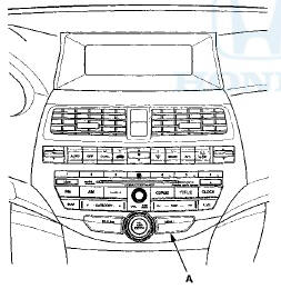
3. Turn the selector knob (A) to select ZONE.
4. Press t h e s e l e c t o r knob (A) t o enter y o u r selection.
The d i s p l a y s h o w s t h e c u r r e n t l y selected zone number.
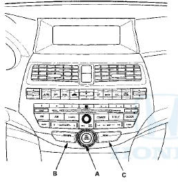
NOTE: If necessary, press t h e RETURN b u t t o n (B) t o return t o t h e p r e v i o u s d i s p l a y . Pressing t h e MENU b u t t o n (C) cancels t h e electrical compass s e t t i ng mode.
5. F i nd t h e zone f o r y o u r area o n t h e m a p . If t h e correct zone is n o t s h o w n , t u r n t h e selector knob to cycle t he zone list u p o r d o w n .
6. Once t h e correct zone is displayed, press t h e selector knob. The display t h e n returns t o n o r m a l .
7. T u r n t h e selector k n o b t o select CALIBRATION.
8. Press the selector knob to enter your selection. The display shows PUSH CAL START.
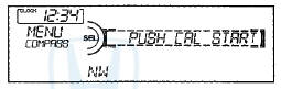
9. Press the selector knob, the compass display will blink and the CAL indicator is shown.
10. When the calibration is successfully completed, the CAL indicator goes off and the compass display will stop blinking and show an actual heading.
NOTE: • While setting, pressing the RETURN button returns to the previous display. Pressing the MENU button (A) cancels the compass setting mode.
• The audio system is not related to the compass system. Even if the compass system is calibrating, the display returns to the normal display which you selected last.
• Do this procedure in an open area, away from buildings, power lines, and other vehicles.
 Circuit Diagram
...
 Electrical Compass Unit Input
Test
Electrical Compass Unit Input
Test
1. Remove the rear shelf (see page 20-128).
2. Loosen the bolts (A), then pull out the electrical compass unit bracket (B).
3. Disconnect the 6P connector (C) and remove the mounting bolt ( D ) ...
See also:
Intermediate Shaft Removal
1. Drain the transmission fluid. Reinstall the drain plug
using a new sealing washer:
-Manual transmission (see page 13-5)
-Automatic transmission (see page 14-192)
2. Remove the right driveshaft ...
Compass Calibration
The compass may need to be
manually calibrated after exposure to
a strong magnetic field. If the
compass seems to be continually
showing the wrong direction and is
not self-calibrating, or ...
Drive Belt Inspection
1. Inspect the belt for cracks or damage. If the belt is
cracked or damaged, replace it (see page 4-30).
2. Check the position of the auto-tensioner indicator's
pointer (A) is within the standard ...